Ahaching the throttle control, Attaching the brake cable, Securing the cables – MTD 110A508R000 User Manual
Page 7: Recoil starter rope assembly
Attention! The text in this document has been recognized automatically. To view the original document, you can use the "Original mode".
THBOTTUE
=IGURE 4.
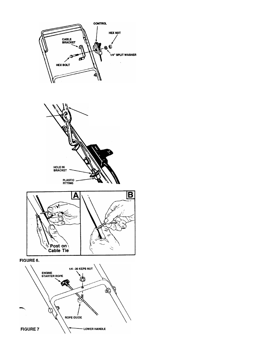
AHACHING THE THROTTLE CONTROL
The throttle control cable is attached to the engine. Attach
the throttle control to the left side of upper handle as follows
(See Fig. 4).
1 Route the throttie control cable inside the iegs and
beneath the upper bar of the lower handle.
2.
Place cable bracket against left side of upper handie,
lining up the hole in the bracket with the bottom hole
in upper handle. Place 1/4" hex bolt through cable
bracket and handle, from the inside to the outside.
3.
Place throttle control on the hex bolt (outside of upper
handle), with the throttie iever facing upward. Se
cure with spiit washer hex nut.
r nmNG
BLADE
CONTROL
HANDLE
FIGURE 5.
ATTACHING THE BRAKE CABLE
1. The brake cable is attached to the engine, and has a
"Z" fitting on the loose end. Route the brake cable
below the lower handle. Place end of cable through
the hole in the bracket as shown (See Fig. 5). Be
careful notto bend orkinkthecable at anytime. Push
the plastic fitting until it locks into the hole in the
bracket.
A
WARNING: Brake cable must be assembled
as shown for proper blade brake operation.
2. Hook the "Z" end of the brake cable into the hole in
the blade control handle from the inside to the
outside as shown (See Fig. 5).
SECURING THE CABLES
Secure all cables to the handle as follows.
1.
Insert posts on cable ties into holes provided on the
left side of the handle, one on the upper handle and
two on the lower handle. The holes may be either on
the inside or outside of the handles. See figure 6A.
2.
Secure the cables with the cable ties. See figure 6B.
3.
Trim excess ends of cable ties.
RECOIL STARTER ROPE ASSEMBLY
1.
Attach starter rope to lower handle with supplied
rope guide (J-bolt) and 1/4-20 hex keps lock nut as
shown See Figure 7. NOTE: If additional rope is
required to complete assembly, pull back engine
control bail lever on upper handle and hold while
slowly pulling additional rope out of engine as
needed. Place rope guide around starter rope and
through lower handle. Tighten securely with lock nut.