Assembly instructions – MTD 110A508R000 User Manual
Page 6
Attention! The text in this document has been recognized automatically. To view the original document, you can use the "Original mode".
IMPORTANT: This unit is Shipped M^ITHOUT GASOLINE or OIL. After assembly, service engine with
gasoline and oil as im^ructed in the separate engine manual packed with your unit.
NOTE: Reference to right or I ;ft hand side of the mower is observed from the operating position.
ASSEMBLY INSTRUCTIONS
Tools Required for Assembly
(1) Pair of Pliers
(2) 7/16" Wrenches*
(2) 1/2" Wrenches*
(1)9/16" Wrench*
* Or 6" Adjustable Wrenches.
UNPACKING
1
.
Remove the lawn mower from the carton by opening
the top flaps and lifting the unit out. Be careful of the
staples. Make certain all parts and literature have
been removed from the carton before the carton is
discarded.
REMOVE CARDBOARD
FIGURE 1.
2.
Disconnect and ground the spark plug wire against
the engine. Check beneath the deck for any card
board packaging. Remove if present.
3.
Stretch out ail control cables on the floor to rear of
mower. Be careful not to bend or kink the cables at
any time during assembly.
4.
Remove page four from this manual and lay the
contents of the hardware pack on the illustration for
identification.
FIGURE 2.
5.
The chute deflector on your mower is held in an_
upright position by a pad for shipping purposes onl
This shipping pad must be removed and discarded
before the mower is put into operation. See figure 1.
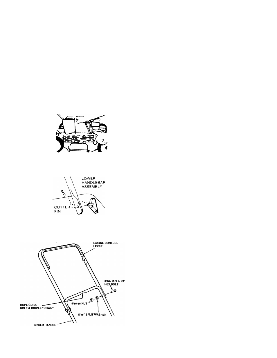
ATTACHING THE LOWER HANDLE
1.
Position lower handle so rope guide mounting hole
and dimple, on handle cross bar, are facing down
wards. See figures.
2.
Slip one leg of lower handle onto the pin of one of the
attaching brackets on the mower base. Apply inward
pressure on the other leg of the handle and snap over
the pin of the other attaching bracket. Secure with
cotter pins supplied. See figure 2.
ATTACHING THE UPPER HANDLE
1.
Position upper handle assembly so the engine con
trol lever is on top side of the handle and attach to
lower handle with (2) 5/16-18x1 -1 /2" hex head bolts,
5/16" split washers and 5/16-18 nuts. See Fig. 3.
FIGURE 3.