Assembly, To remove mower from carton, How to set-up your lawn mower – MTD 110-017R000 User Manual
Page 6: Attach lower handle (see fig. 1), Attach starter rope to handle (see fig. 3)
Attention! The text in this document has been recognized automatically. To view the original document, you can use the "Original mode".
ASSEMBLY
Your lawn mower has been completely assembled i it the
factory except for the handles and safety chute gu ard.
TO REMOVE MOWER FROM CARTON
•
Remove loose parts if included with mower, (i.e.
handles, chute guard, hardware pack, etc.).
•
Cut down corners on one end of carton and la^ end
down flat.
•
Remove packing material.
•
Roll mower out of carton and check carton thor
oughly for loose parts.
HOW TO SET-UP YOUR LAWN MOWER
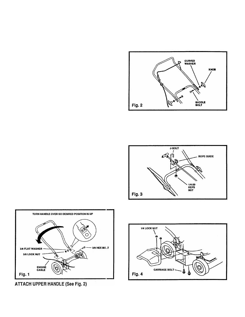
ATTACH LOWER HANDLE (See Fig. 1)
Your mower handle can be raised or lowered for your
mowing comfort by assembling the lower handle ii i the
desired position. This must be done before yoi as
semble the upper handle.
•
Lay upper handle on work surface behind mowe ■ and
position engine cable so it is on the outside of jeck
mounting bracket as shown.
•
We recommend attaching the handles in the "H GH"
position. This will put the upper handle approxi
mately 37 inches up from the ground with the wt leels
adjusted in the mid-position. The "LOW" pos ition
measurement is approximately 34 inches.
•
Position lower handle in desired position by turning
handle over so desired "HIGH" or "LOW" readi ig is
upwards.
•
Attach loosely one leg of lower handle to handle
bracket with 3/8-16 x 3/4" hex bolt, 3/8" flat washer
and 3/8-16 lock nut as shown. Do not tighten.
NOTE:
Be sure hex bolt is assembled from outside of
bracket as shown.
•
Repeat assembly for opposite side of lower ha idle.
•
Now tighten all bolts and nuts securely on both t ides
of lower handle.
Tighten knobs securely.
Secure engine cable to lower handle with plastic tie
(See Fig. 5).
ATTACH STARTER ROPE TO HANDLE
(See Fig. 3)
Assemble starter rope to lower handle cross bar, from
eithertop or bottom side as desired, with "J" bolt, two (2)
rope guide halves and 1/4-20 hex nut. Tighten nut
securely with 7/16" wrench.
ATTACH SAFETY CHUTE GUARD (See Fig. 4)
Assemble safety chute guard to mower with two (2) each
carriage bolts and 1/4" locknuts as shown. Tighten nuts
securely with 7/16" wrench.
Position upper handle so operator presence control
bar is on top and assemble to lower handle with
saddle bolts, curved washers and knobs as shown.
A
CAUTION: DO NOT RUN YOUR LAWN MOWER
WITHOUTCHUTEGUARDORAPPROVEDGRASS
CATCHER IN PLACE.