Figures – MTD 246-596-000 User Manual
Page 5
Attention! The text in this document has been recognized automatically. To view the original document, you can use the "Original mode".
HANDLE
THROUGH
SLOT IN FRAME
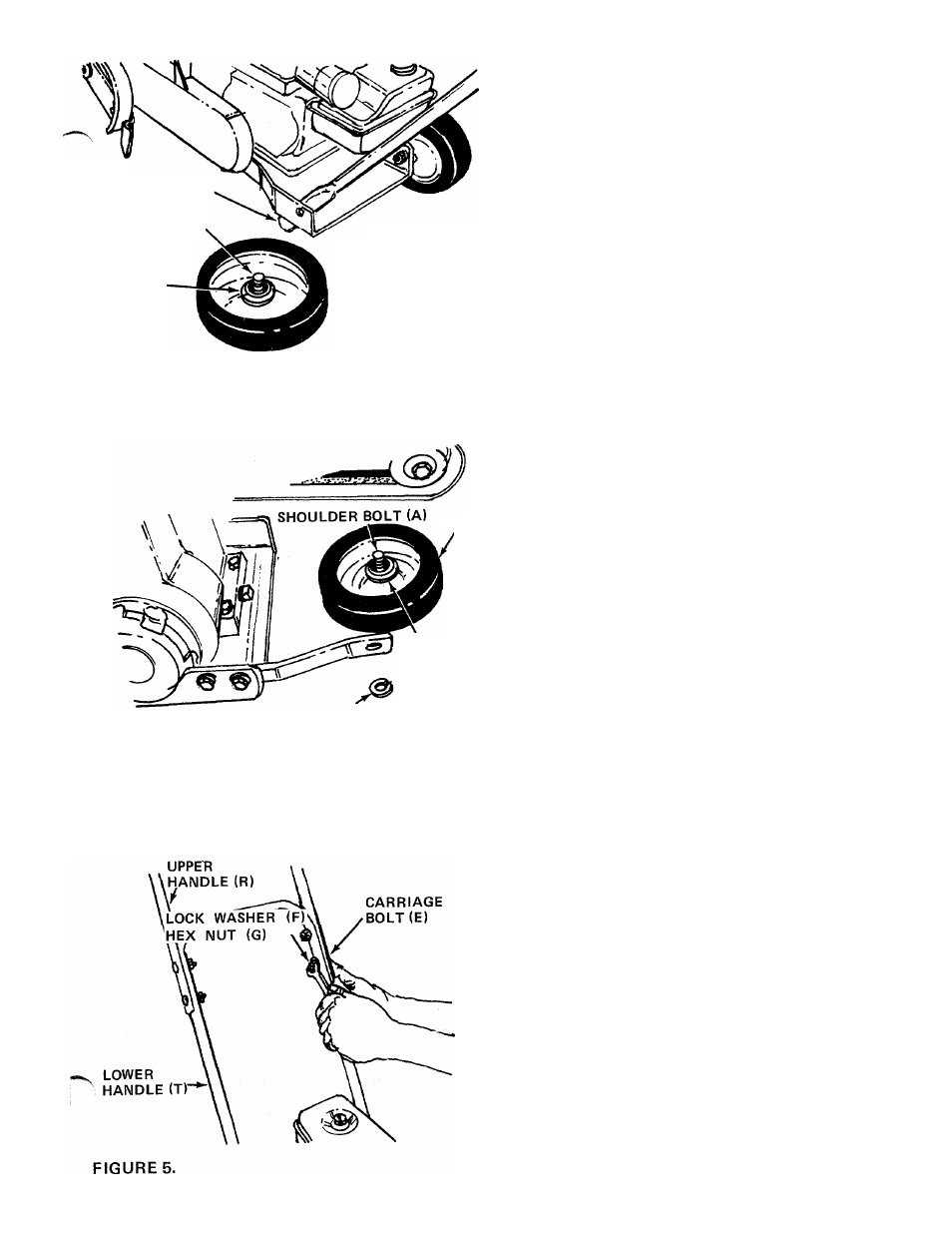
SHOULDER
BOLT (A)
BELLEVILLE
WASHER (B)
HEX NUT (D)
t
2
.
3.
4.
Place lower handle into the slots in the rear
frame. See figure 3.
Line up holes in handle with holes in frame.
See figure 3.
Secure rear wheels (P) and lower handle (M) to
frame with shoulder bolts (A), belleville washers
(B) (cupped side of washer against the frame),
lock washers (C) and hex nuts (D). See figure 3.
LOCK
WASHER (C)
FIGURES.
FRONT
WHEEL
BELLEVILLE
WASHER (B)
Assemble the front wheel (0) as shown in figure
4.
Place shoulder bolt (A) through wheel, then
belleville washer (B) (between wheel and frame,
cupped side against the frame). Secure with lock
washer (C) and hex nut (D). See figure 4.
LOCK WASHER (C)
HEX
NUT,
(D)
FIGURE 4.
6. Assemble the upper handle (R) to lower handle.
Place the head of carriage bolts (E)to the outside
of handle. Secure with lock washers (F) and
and hex nuts (G). See figure 5.