Note, Assembly, Contents of hardware pack (see figure 1) – MTD 216-031-000 User Manual
Page 4
Attention! The text in this document has been recognized automatically. To view the original document, you can use the "Original mode".
NOTE
Reference to left or right side of the
tiller is determined from behind the
unit in the operating position.
ASSEMBLY
B-
c-
—
FIGURE 1.
NOTE
This unit is shipped WITHOUT GAS
OLINE or OIL. After assembly, see
separate engine manual for proper
fuel and engine oil recommenda
tions.
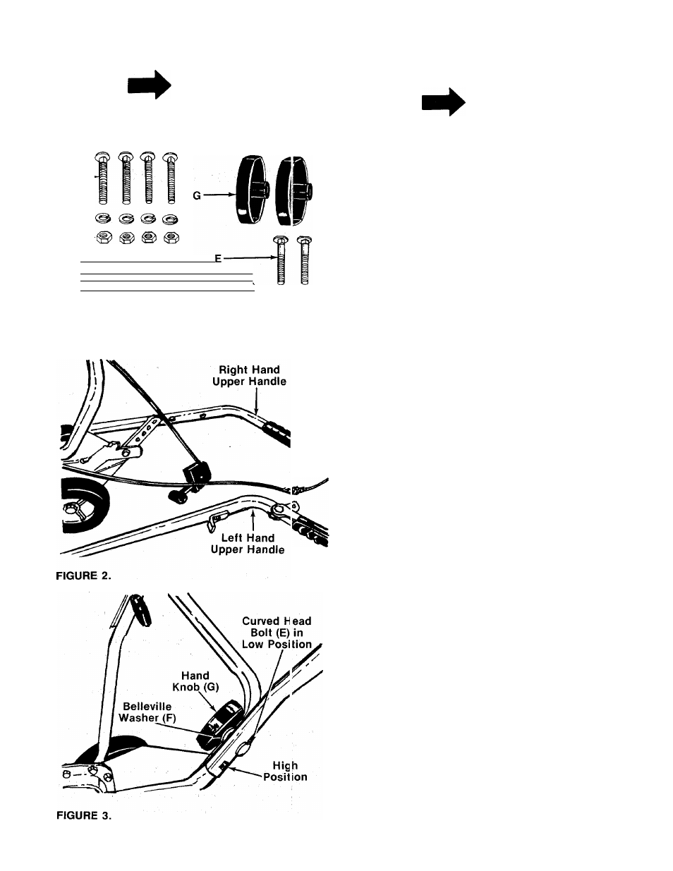
■Contents of Hardware Pack (See Figure 1):
A (4) Carriage Bolts 5/16-18 x IV
2
" Long
Lock Washers 5/16" I.D.
Hex Nuts 5/16-18 Thread
Cable Ties
Curved Head Bolts
Belleville Washers 5/16" I.D.
Hand Knobs
Self-Tapping Screw (Not Shown)
Loose Parts in Carton:
(1) Upper Handle—R.H.
Ò) Upper Handle—L.H.
(1) Handle Panel
Tools Required
(2)
Vz"
open end or box wrenches
1. Remove the tiller from the carton. Make certain all
parts and literature have been removed before the
carton is discarded.
2.-Extend the control cables and place on the floor.
-----Be careful not to bend or kink the cables.
B
C
D
E
F
G
H
(4)
(4)
(
2
)
(
2
)
(
2
)
(
2
)
(
1
)
3. There are eight positions for the upper
handles. Place left hand upper handle (with clutch
grip and cable support bracket already assembl
ed) in position on lower handle, selecting hole for
either high or low position. Secure with curved
head bolt (E), belleville washer (F) (cupped side
— against the handle) and hand knob (G). See figure
3. Do not tighten at this time. Assemble right hand
upper handle in the same manner.