MTD 215-355AB2 User Manual
Page 9
Attention! The text in this document has been recognized automatically. To view the original document, you can use the "Original mode".
REF.
NO.
PART
NO.
COLOR
CODE
DESCRIPTION
NEW
PART
REF.
NO.
PART
NO.
COLOR
CODE
DESCRIPTION
NEW
PART
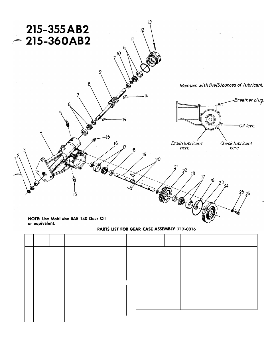
1
716-0119
Snap Ring for .750" Dia. Shaft
15
737-0103
Sq. Hd. Pipe Plug
%"
Thd.
2
721-0100
Oil Seal—.750" Shaft
16
721-0102
Oil Seal Double Lip 1" Shaft
3
748-0106
Sleeve Brg. .752" I.D.
17
741-0108
Roller Brg. 1" Bore
4
717-0226
Gear Case
18
711-0131
Spacer 1.005 I.D. x 1.390 O.D.
5
737-0102
Sq. Hd. Pipe Plug with Vent %'
19
711-0133
Tine Shaft 1" Dia.
Thd.
20
714-0103
*91 Woodruff Key Vz" x %" Dia.
6
741-0107
Roller Brg. .750" Bore
21
716-0102
Snap Ring for 1" Shaft .
7
711-0469
Spacer .755" I.D. x 1.265" O.D.
22
717-0315
Worm Wheel (Stencil "
20
")H*-Ul
8
738-0170
Worm Shaft %" Dia.
23
735-0101
O-Ring 3.62
X
3.88
9
717-0312
Worm (Stencil "20")
24
717-0227
Bearing Cap—Bolt-on Type
10
716-0101
Snap Ring for .750" Dia. Shaft
25
736-0119
L-Wash. 5/16" Scr.*
11
735-0100
O-Ring 2.12
X
2.38
26
710-0371
Hex Scr. 5/16-18
X.
88" Lg.—
12
10583
Brg. Adjustment Cap
Special
13
714-0474
Cotter Pin Va" Dia. x .75" Lg.*
14
714-0126
#9 Hi-Pro Key 3/16x%"“Dia
.
*For faster service obtain standard nuts and bolts locally. If these items
Hdn. 1
cannot be obtained locally, order by part number and size as shown
»A