Note, Assembly, Tine assembly – MTD 215-355AB2 User Manual
Page 2: Wheel assembly
Attention! The text in this document has been recognized automatically. To view the original document, you can use the "Original mode".
1.
Your tiller is a precision piece of power equipment.
Exercise extreme caution at ail times.
2.
Do not attempt to start engine with the clutch con
trol in the engaged or FORWARD position.
3.
Stand clear of tines when starting engine. Never
stand in front of, or work on tines while the en
gine is running.
4. NEVER place hands or feet in the vicinity of the
tines while the engine is running.
5. Always stop engine when tiller is not in actual use.
6. Always disconnect spark plug wire during repairs
or refueling operations.
7. Do not fill gas tank while engine is running. Do not
spill gasoline on hot engine.
Your rotary tiller is designed to take the work out of
gardening and other related chores. It can be used
for seed bed preparation, tilling, cultivating, furrow
ing, composting and mulching. Like any other piece
of power equipment, it requires a certain amount of
care and maintenance. In return for this, it will give
a maximum of service and efficiency. Read these in
structions
carefully
before
assembling
or
operating
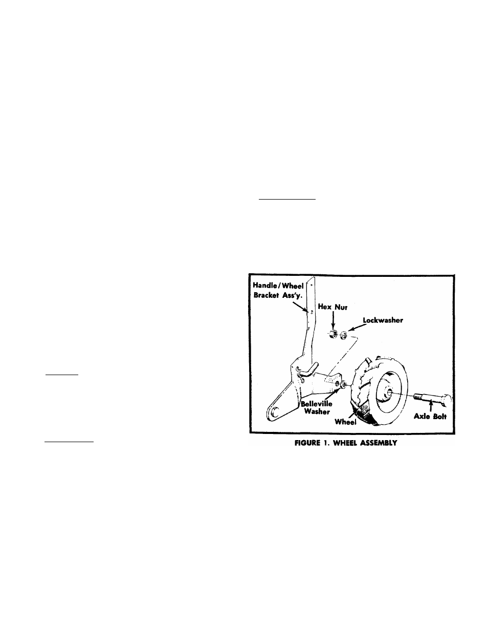
will obtain long, efficient service and trouble-free operation. NOTE The engine is shipped without oil in ASSEMBLY Your rotary tiller is shipped complete in a single car ner described below. TINE ASSEMBLY Step 1. The inner tine assemblies are already assem bled to the tiller. Step 2. The outer tine assemblies are inverted on the tine shaft and MUST be removed and turned WHEEL ASSEMBLY Insert axle bolt into wheel. Place Belleville washer on threaded part of axle bolt. Crown of washer should be fasten with lockwasher and hex nut. See figure 1. Step 3. Remove the outer tine assembly and turn around so that the sharp edge of the tines enters the soil first. Secure with bolt and lock nut. See page 12.
the crankcase. See engine manual for
correct type and amount.
ton. The tines, wheels, handle, controls, depth bar and
tailpiece are to be assembled. This is done in the man
around.
positioned towards the wheel. Insert axle bolt in wheel
mounting hole of handle/wheel bracket assembly and