Warning – Troy-Bilt 645A User Manual
Page 12
Attention! The text in this document has been recognized automatically. To view the original document, you can use the "Original mode".
Section 3: Features and Controls
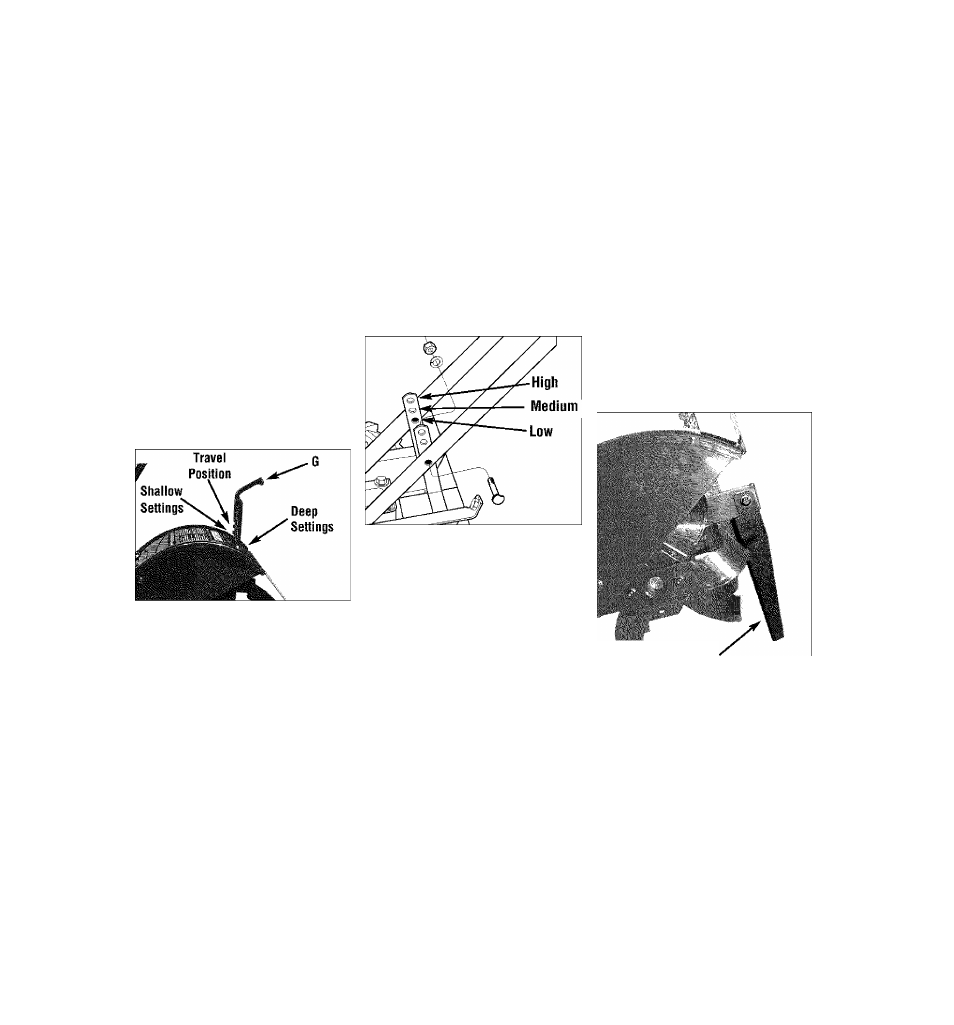
Depth Regulator Lever
This lever (G, Figure 3-5) controls the
tilling depth of the tines. Pul! the lever
straight back and slide it up or down to
engage the notched height settings.
The highest notch (lever all the way
down) raises the tines approximately 1-
1/2“ off the ground. This “travel” setting
allows the tiller to be moved without the
tines digging Into the ground. Also use
this setting when starting the engine.
Move the lever upward to increase the
tilling depth. The lowest notch allows a
tilling depth of approximately 6'-8",
depending on soil conditions.
For best results, begin tilling at the
deepest depth possible without causing
the tiller to bog down. Increase the tilling
depth from one pass over the soil to the
next.
Figure 3-5: Depth regulator lever.
Handlebar Height Adjustment
The handlebar height Is adjustable to
three different settings (see Figure 3-6).
As a general rule, adjust the handlebars
so they are at waist level when the tines
are 3"-4“ Into the soil.
To Adjust the Handlebai^:
1. Stop the engine, disconnect the spark
plug wire from the spark plug and allow
the engine to cool.
2.
Remove the screws, lockwashers and
nuts, reposition the handlebars, and
reinstall the hardware.
Figure 3-6: Handlebar height adjustment.
Anti-Reverse Stake
This stake is located at the rear of the
transmission, under the tine hood (see H,
Figure 3-7). Its purpose is to automati
cally help prevent the counter-rotating
tines from letting the tiller back up in the
direction of the operator if the tiller
wheels had been inadvertently left in the
FREEWHEEL position. In this situation,
the Anti-Reverse Stake will be forced
down into the ground, lifting the tines
upward out of the soil and helping
prevent backward motion of the tiller.
The Anti-Reverse Stake requires no adjust
ment, but should be inspected before
each tllier use to verify that it swivels
freely. Remove any clogged materials
(dirt, roots, rocks, etc.) that prevent the
Anti-Reverse Stake from swinging freely.
A
WARNING
.................................. H
• Place the Depth Regulator
Lever in the “travel”
___________________
position before starting the
..................................................
Figure 3-7: Anti-Reverse stake.
engine.
This
position
prevents
the
tines
from
touching the ground untii you
are ready to begin tiiiing.
rnMTHni Q
Failure to foilow this warning ................................................................................ cnume uun i nuLO
couid resuit in personal injury
......................................................................................... Refer to the engine manufacturer’s Engine
or property damage.
Owner’s Manual (included in the tiller lit
erature package) to identify the controls
on your engine.
IMPORTANT:
The control for stopping the
engine is located on the engine.
12