MTD TMO-33849A User Manual
Page 9
Attention! The text in this document has been recognized automatically. To view the original document, you can use the "Original mode".
i
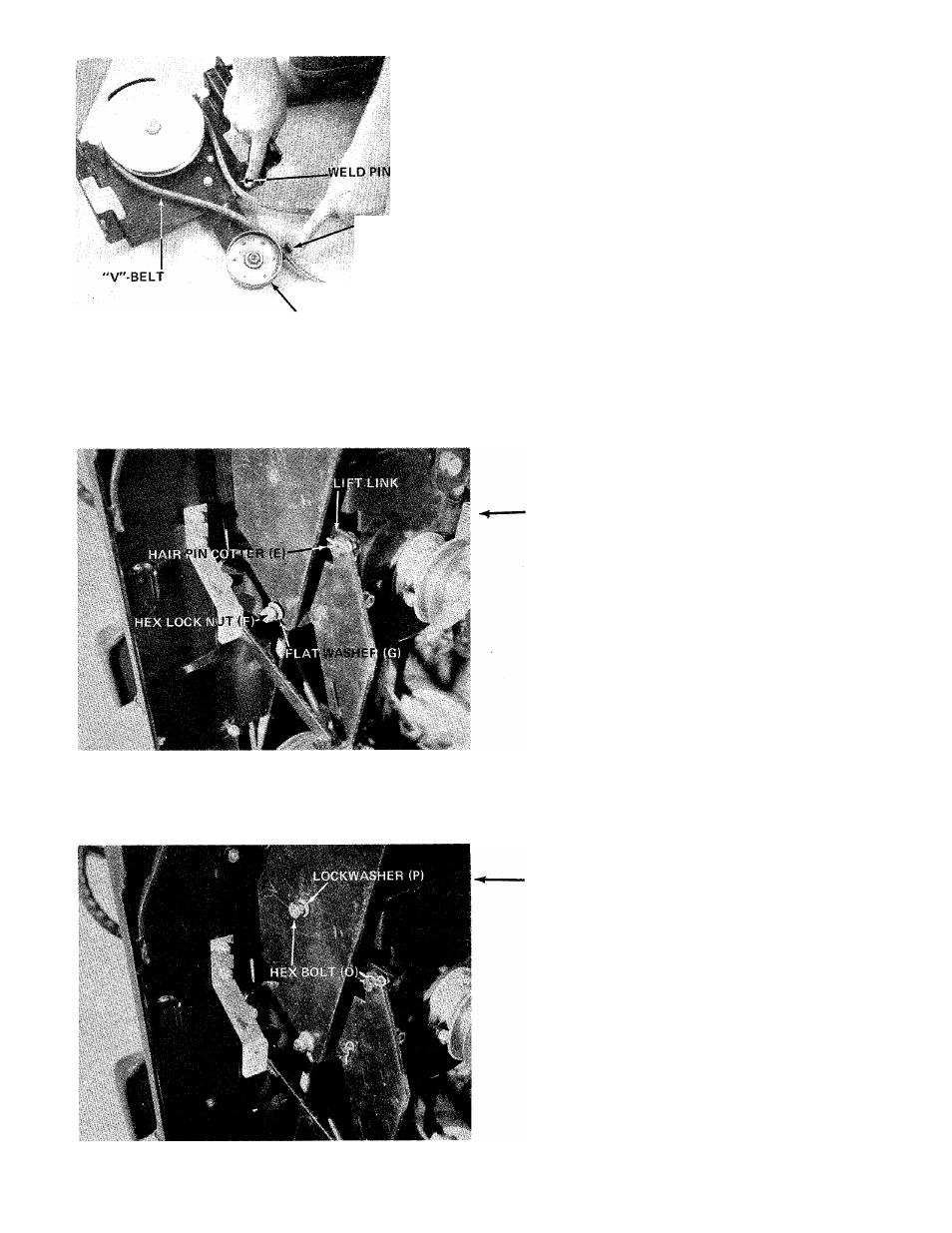
BELT GUARD
14. Be sure belt on idler assembly is in position on
idler pulley between belt guard and weld pin as
shown in figure 16.
IDLER PULLEY
FIGURE 16
15. Place the idler assembly in position between
channel supporting brackets and start hex lock
nuts (F) and flat washers (G) over weld studs as
shown in figure 17.
16. Place lift handle links down through idler
assembly and secure to linkage brackets with
hair pin cotters (E). See figure 17.
FIGURE 17
17. Start hex bolts (O) and lock washers (P) through
center of channel support and idler assembly. See
figure 18.
18. Tighten nuts and bolts in steps 15 and 16
securely with wrenches.
FIGURE 18