Operation, Pre-start preparations, To start engine – MTD 24687S User Manual
Page 9: Adjustments, Height adjustment, Caution, Revolving blades-keep hands away from all openings
Attention! The text in this document has been recognized automatically. To view the original document, you can use the "Original mode".
OPERATION
PRE-START PREPARATIONS
"^vice engine with gas and oil. See engine manual
xked with vacuum for complete instructions for
care and maintenance of engine. READ DIREC
TIONS CAREFULLY.
A
CAUTION
REVOLVING BLADES-KEEP
HANDS AWAY FROM ALL
OPENINGS
TO START ENGINE
After the engine has been properly fueled and oiled
(refer to engine operating and maintenance instruc
tions), start engine following the instructions below.
1. Move throttle control lever on engine to START
position.
2.
Crank engine. Pull recoil with quick firm pull.
Do not pull out so far the rope stops with-a jerk
as this will cause rope failure. Do not allow rope
and handle to snap back into place.
3.
After two or three full firm pulls on recoil (or as
soon as engine fires), move speed control to
RUN position.
4.
Self Propelled Models Only - To engage the drive
mechanism, squeeze the clutch grip against the
upper handle. Release the clutch grip to stop the
forward motion.
TO STOP ENGINE
1. To stop engine, move throttle control lever to
STOP position.
2.
Disconnect spark plug wire and ground to prevent
accidental starting while equipment is unattended.
Operate a new engine at intermediate speeds and light
load for the first few hours as you would a new
automotive engine.
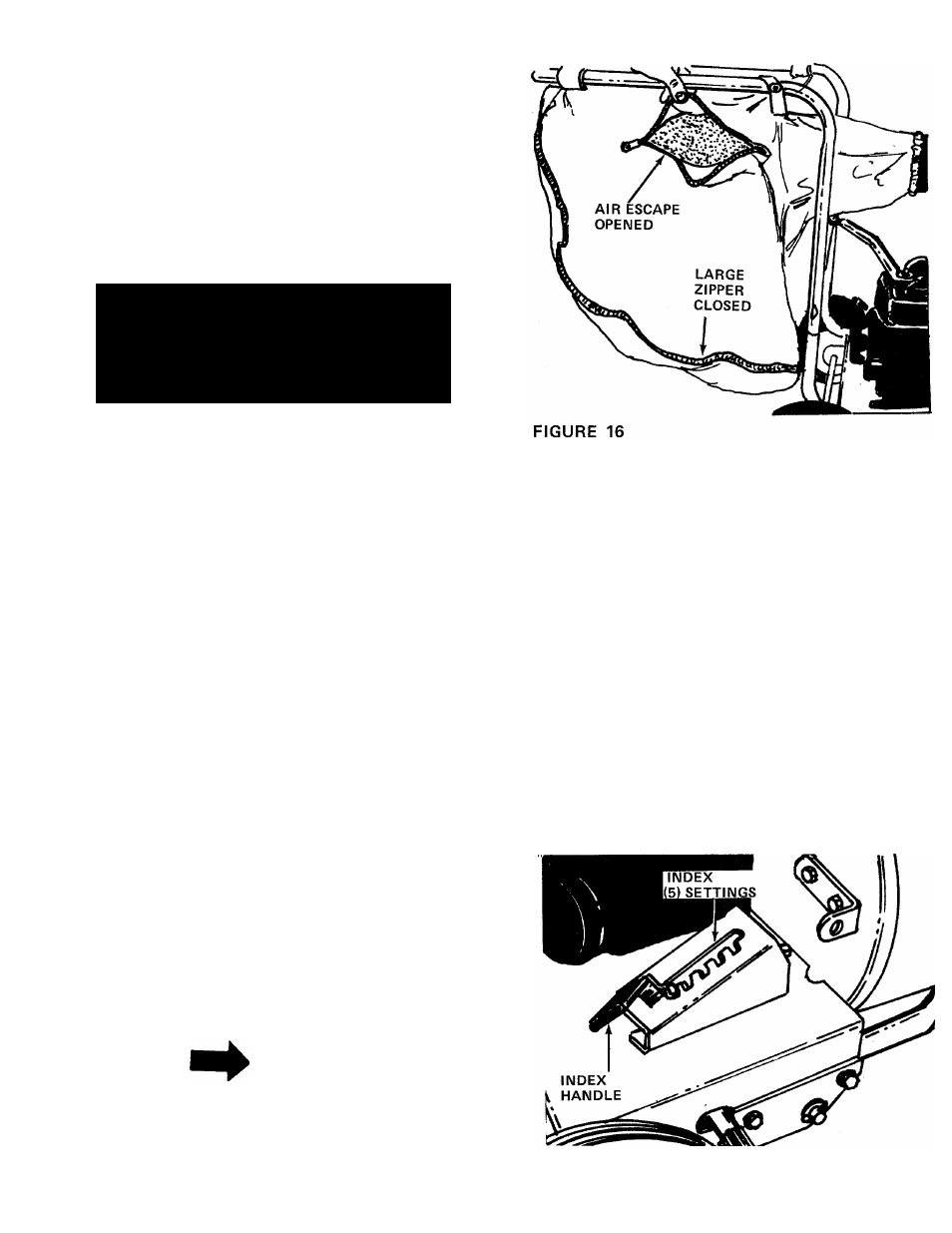
IMPORTANT
The vacuum bag may have an air escape
located on the upper right hand side.
See figure 16. The air escape can be
opened if the vacuum is operated in
wet, sandy or muddy conditions.
ADJUSTMENTS
A
CAUTION
Do not at any time make any adjust
ment to the unit without first stopping
engine and disconnecting spark plug
wire.
HEIGHT ADJUSTMENT
To adjust the height of the nozzle, stand on the right
hand side of vacuum and move the index handle
towards the engine. Move handle towards rear of unit
to lower height. Move the handle forward to raise the
height. See figure 17.
FIGURE 17