Assembly instructions for tow bar kit (optional) – MTD 24687S User Manual
Page 8
Attention! The text in this document has been recognized automatically. To view the original document, you can use the "Original mode".
5.
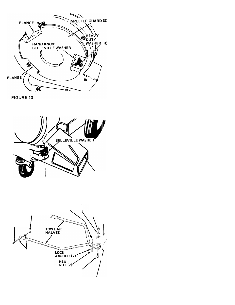
Lift up and out on the housing and rotate it 105°
clockwise. Chute opening should be to the righ^
hand side when viewed from the front of unit.
See figure 13.
6.
Place the impeller guard (S) into flanges on front
of housing. Line up hole in guard with hole on
housing. Secure with one hand knob, belleville
washer and heavy flat washer (H). See figure 13.
HAND KNOB
DIRECTIONAL
DISCHARGE
ASSEMBLY (R)
7. Place the directional discharge assembly (R) over
chute opening. Secure with two hand knobs and
belleville washers. See figure 14.
FIGURE 14
HEX
NUT (W)
TRUSS
MACHINE
SCREW (X),
HEX
BOLT(U)
BELLEVILLE
WASHER (AB)
HEX JAVI
LOCK ^ UT
(AC)
HI ГСН
PLATE
SHOULDER
SPACERS(V)
SHOULDER'
BOLT (AA)
BELLEVIL-E
WASHER (ДВ)
FIGURE 15
ASSEMBLY INSTRUCTIONS
for Tow Bar Kit (Optional)
1. Remove the self-tapping screws on each side of
frame. Refer to drawing on page 12, reference
number 42.
2.
Place tow bar half in position on frame. Place
one shoulder spacer (V) between frame and
tow bar. Next, place shoulder spacer (V) and hex
bolt (U) through tow bar and frame. Secure with
hex nut (W). See figure 15. Repeat for other side.
3. Secure the two tow bar ends together with truss
machine screws (X), lock washers (Y) and hex
nuts (Z). See figure 15.
To attach the tow bar to a hitch, place the shoulder
bolt (AA) up through the tow bar. Place one bellevillt
washer (AB) on the shoulder bolt, then the hitch
place and the other belleville washer. Cupped side of
the washers must be against the hitch plate. Secure
with hex jam lock nut (AC). See figure 15.