Figure 1, 1t f j, Assembly – MTD 24687S User Manual
Page 4: Instructions, Contents of hardware pack (see figure 1), Loose parts in carton (see figure 2), 1 t f j, Assembly instructions, K-*l
Attention! The text in this document has been recognized automatically. To view the original document, you can use the "Original mode".
H
® i
I
FIGURE 1
1T f J ®®@®
@ © ® •■'^ -
K-*l
M
ASSEMBLY
INSTRUCTIONS
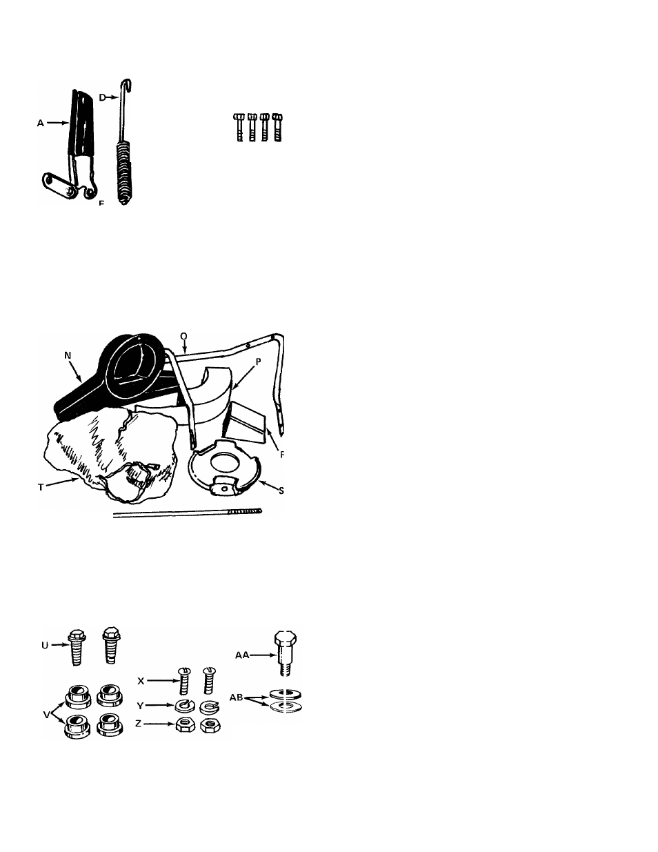
CONTENTS OF HARDWARE PACK
(See figure 1)
A
(1) Clutch Grip Assembly*
B
(1) Hair Pin Cotter*
C
(1) Clevis Pin*
D
(1) Extension Spring*
E
(1) Lock Nut 1/4-20 Thread*
F
(3) Hand Knobs
G
(3) Belleville Washers
H
(1) Heavy Flat Washer
I (4) Hex Bolts 1/4-20 x 1.75" Long
J
(4) Hex Lock Nuts 1/4-20 Thread
K
(2) Stud Pins
L
(2) Push-on Speed Nuts
M (1) Hex Jam Nut 1/4-20 Thread*
LOOSE PARTS IN CARTON
(See figure 2)
N
(1) Nozzle
0
(1) Upper Handle
P
(1) Air Duct Assembly
Q
(1) Clutch Rod*
R
(1) Directional Discharge Assembly
S
(1) Impeller Guard
T
(1) Bag
*Self-Propelled Models Only.
FIGURE 2
TOW BAR KIT- Standard with push models.
w-
(See figure 3) Optional with self-propelled
U
(2)
Hex Bolts 5/16-18
X
1.00" Long
V
(4)
Shoulder Spacers
w
(2)
Hex Nut 5/16-18 Thread
X
(1)
Truss Machine Screw 1/4-20 x .75"
Y
(1)
Lock Washer 1/4" I.D.
z
(1)
Hex Nut 1/4-20 Thread
AA
(1)
Shoulder Bolt
AB
(2)
Belleville Washers 3/8" I.D.
AC
(1)
Hex Jam Lock Nut 3/8-16 Thread
(2)
Tow Bar Halves (Not Shown)
FIGURE3