To adjust motion control lever (see fig. 27), Transmission removaureplacement, To adjust steering wheel alignment – Poulan 159759 User Manual
Page 24: Front wheel toe-in/camber, To remove wheel for repairs (see fig. 28), Service and adjustments
Attention! The text in this document has been recognized automatically. To view the original document, you can use the "Original mode".
SERVICE AND ADJUSTMENTS
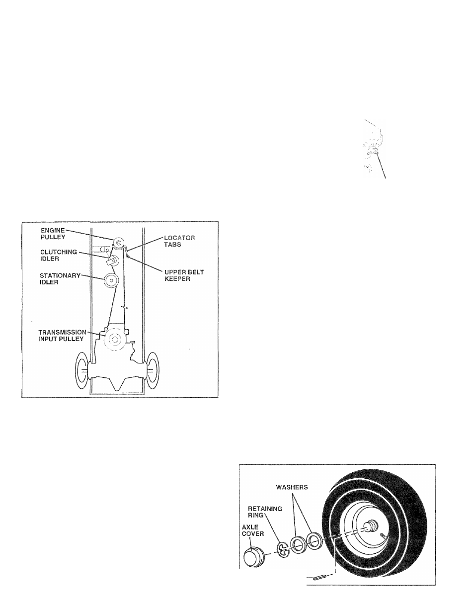
TO REPLACE MOTION DRIVE BELT
(See Fig. 26)
Park the tractor on level surface. Engage parking brake.
For assistance, there is a belt installation guide decal on
bottom side of left footrest.
•
Remove mower (See “TO REMOVE MOWER” in this
section of this manual.)
•
Remove upper belt keeper.
•
Remove belt from stationary idler and clutching idler.
•
Pull belt slack toward, rear of tractor. Carefully remove
belt upwards from transmission input pulley and over
cooling fan blades.
•
Pull belt toward front of tractor and remove downward
from around engine pulley.
•
Install new belt by reversing above procedure.
IMPORTANT: MAKE SURE UPPER BELT KEEPER IS
POSITIONED PROPERLY BETWEEN LOCATOR TABS.
FIG. 26
TO ADJUST MOTION CONTROL LEVER (See
Fig. 27)
The motion control lever has been preset at the factory and
adjustment should not be necessary.
If for any reason the motion control lever will not hold its
position while at a selected speed, it may be adjusted at the
friction pack located on the right side of transmission.
•
Park tractor on level surface. Stop tractor by turning
ignition key to “OFF” position, and engage parking
brake.
•
Adjust motion control lever by tightening adjustment
locknut one half (1/2) turn.
NOTE: If for any reason the effort to move the motion
control lever becomes too excessive, reverse the above
adjustment procedure by loosening locknut 1/4 to 1/2 turn.
Road test tractor after adjustment and repeat procedure if
necessary.
TRANSMISSION REMOVAUREPLACEMENT
Should your transmission require removal for service or
replacement, it should be purged after reinstallation and
before operating the tractor. See “PURGE TRANSMIS
SION” in the Operation section of this manual.
ADJUSTMENT
LOCKNUT
FIG. 27
TO ADJUST STEERING WHEEL ALIGNMENT
If steering wheel crossbars are not horizontal (left to right)
when wheels are positioned straight forward, remove steer
ing wheel and reassemble per instructions in the Assembly
section of this manual.
FRONT WHEEL TOE-IN/CAMBER
The front wheel toe-in and camber are not adjustable on
your tractor. If damage has occurred to affect the front
wheel toe-in or camber, contact your nearest authorized
service center/department.
TO REMOVE WHEEL FOR REPAIRS
(See Fig. 28)
•
Block up axle securely.
•
Remove axle cover, retaining ring and washers to allow
wheel removal (rear wheel contains a square key - Do
not lose).
•
Repair tire and reassemble.
•
On rear wheels only: align grooves in rear wheel
hub
and
axle. Insert square key.
•
Replace washers and snap retaining ring securely in
axle groove.
•
Replace axle cover.
NOTE: To seal tire punctures and prevent flat tires due to
slow leaks, tire sealant may be purchased from your local
parts dealer. Tire sealant also prevents tire dry rot and
corrosion.
SQUARE KEY
(REAR
WHEEL ONLY) "—”
24
FIG. 28