Troy-Bilt 13076-GTX 20 User Manual
Page 13
Attention! The text in this document has been recognized automatically. To view the original document, you can use the "Original mode".
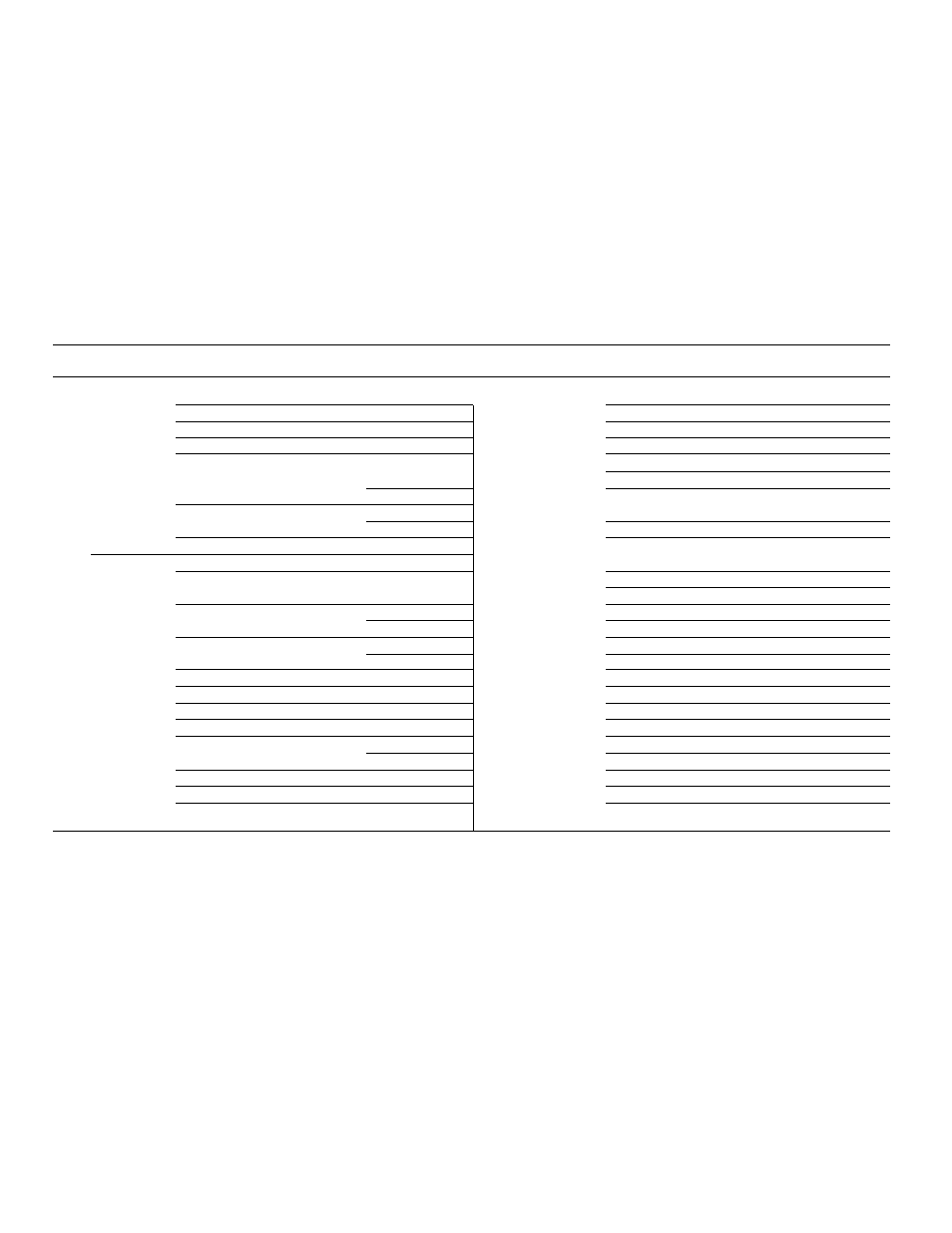
Models 13074 and 13101
Ref.
Part
Description
Qty.
Ref.
Part
Description
Qty.
53
1765531
Cable Tie.................... .......... A/R
209
1767394
Hydraulic Valve..................... ... 1
156
1186391
Flange Nut, 5/16-18....... .......... 4
210
1186316
Hex Head Screw, 1/4-20 x 2...... ... 2
158
1717563
Connector................... .......... 1
211
1186389
Flange Nut, 1/4-20................. ... 15
159
1185737
90° Elbow................... .......... 1
212
1769391
Connector............ ............... ... 2
161
1767741
Tube (Control Valve E to Lift Valve In).... 1
213
1767537
Tube (Tee to Filter In)............. ... 1
164
1767536
Tube (Control Valve A to Tee).
.......... 1
214
1762308
Swivel Tee........................... ... 1
174
1185739
90° Elbow................... .......... 1
216
1767744
Tube (Lift Valve B to
181
1186330
Flange Screw, 5/16-18 x 7/8..
.......... 2
Lift Cylinder, Fixed End)........ ... 1
182
1186330
Flange Screw, 5/16-18 x 7/8...
.......... 2
217
1727233
Connector............................ ... 1
183
1767725
Bearing....................... .......... 2
218
1767745
Tube (Lift Valve A to
184
1761400001 Lift Shaft Assembly.......... .......... 1
Lift Cylinder, Piston End).. ..... ... 1
185
1747509
Hydraulic Cylinder
219
1118554
Retaining Ring....................... ... 2
(Inci. Refs. 550 thru 560).... .......... 1
220
1747512
Cylinder Rod Pin..................... ... 1
186
1752648
Hose (Lift Cylinder Piston End)..... 1
221
1118808
Retaining Ring....................... ... 1
187
1185903
45° Elbow............ ....... .......... 1
550
1729388
Hydraulic Cylinder Tube........... ... 1
188
1755198
Hose (Lift Cylinder Fixed End)
.......... 1
551
1118735
Internal Retaining Ring............ ... 1
196
1708012
Washer....................... .......... 1
552
1185266
Oil Seal............................... ... 1
197
1724703
Cylinder Pin................. .......... 1
553
1186019
Back-Up Ring........................ ... 1
198
1113527
Retaining Ring.............. .......... 2
554
1177395
0-Ring................................ ... 1
201
1755460
Control Lever............... .......... 1
555
1724511
Cylinder Head....................... ... 1
202
1755473
Control Knob................ .......... 1
556
1186018
Back-Up Ring........................ ... 3
203
1771430
Arm Assembly, Control (B, E)
.......... 1
557
1186017
0-Ring................................ ... 2
204
1717897
Hair Pin...................... .......... 1
558
1747043
Hydraulic Cylinder Rod Assembly. ... 1
205
1713457
Drive Pin, 3/16x3/4........ .......... 1
559
1186278
Pipe Plug............................. ... 1
207
1737018
Flange Bearing.............. .......... 2
560
1754414
Replacement Seal Kit (for Ref. 209)...
... N/l
208
1767406
Valve Link................... .......... 1
561
1767404
Control Arm (A)..................... ... 1
(A)
Model 13074- Serial Numbers 130740100101 -
130740100207
N/l
Item not included with the unit, order separately.
(B)
Model 13074- Serial Numbers 130740100208-130740199999
A/R As required.
(C)
Model 13076- Serial Numbers 130760100101 -
130760100377
(D)
Model 13076- Serial Numbers 130760100378-
130760199999
(E)
Model 13101 -Serial Numbers 131010100101 -
131010199999
13