Tine installation, Note, Final clutch adjustment – MTD 219-381-000 User Manual
Page 8: Controls, Throttle control, Forward drive clutch lever, Reverse drive clutch lever, I^note
Attention! The text in this document has been recognized automatically. To view the original document, you can use the "Original mode".
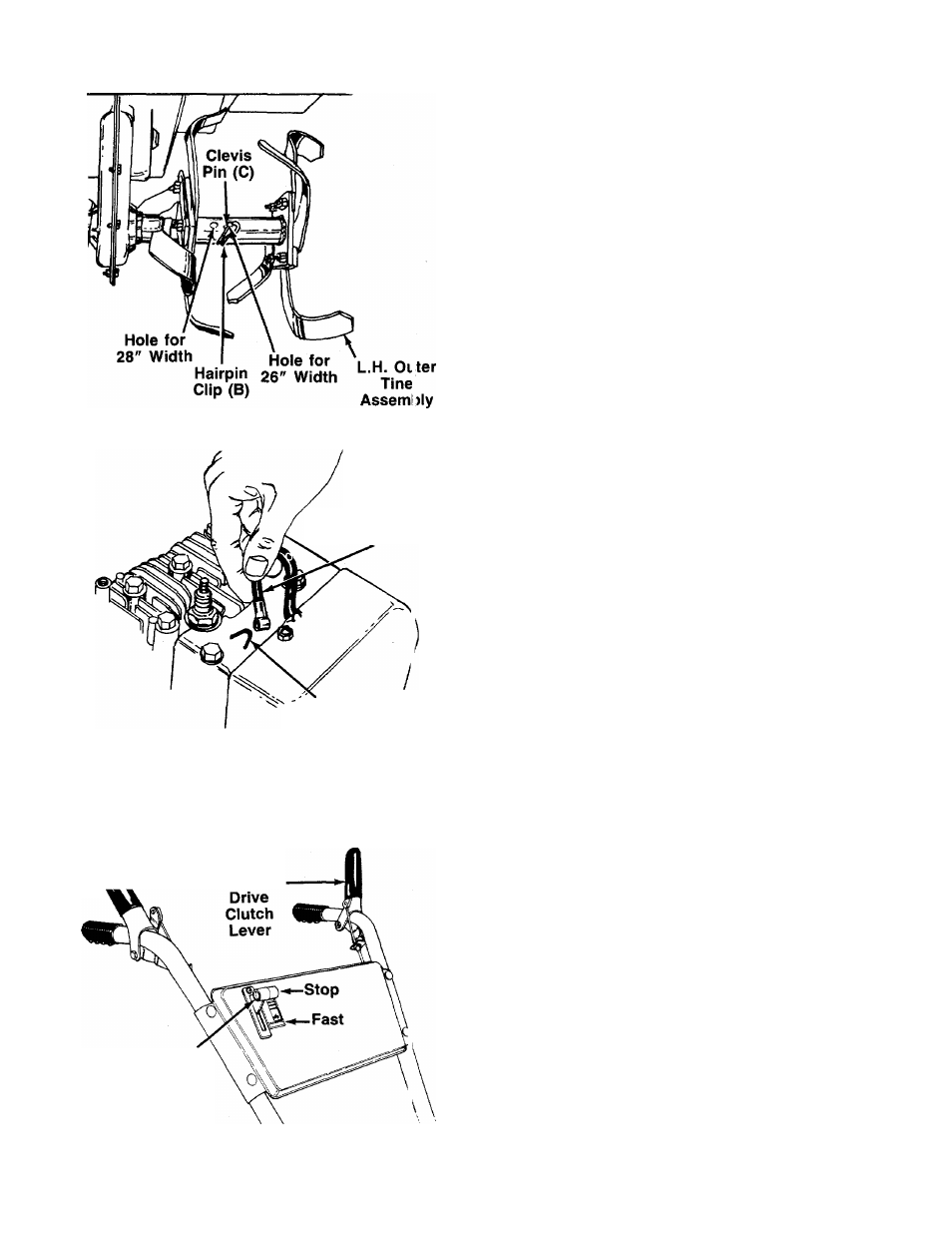
FIGURE 12.
Spark Plug
Wire
{
“V” Slot
on Engine
TINE INSTALLATION
The inner tine assemblies are installed in their correct
position at the factory. Check to be certain the tine
assemblies are on the tine shaft so that the sharp edge
enters the soil first. See figure 12.
1. Align one of the holes in the tine assembly with the
hole in the tine shaft. Using the end hole on the
tine assembly will give a tilling width of 28". Using
the second hole will give a tilling width of 26". See
------ figure 12.
2. Secure with clevis pin (C) and hairpin clip (B).
3. Secure the other tine assembly in the same
manner.
NOTE
FIGURE 13.
Make certain tines are installed so
that the sharp edge of the tines wiii
enter the soii first when in forward
drive.
FINAL CLUTCH ADJUSTMENT
To check the forward and reverse clutch cable adjust
ment, proceed as follows.
1. Disconnect the spark plug wire from the spark plug
to prevent accidental starting. Secure the end of
spark plug wire in the “V” slot on the engine. See
------ figure 13.
2. With both clutch grips released (neutral position),
pull the starter rope several times. The tines
shouid not turn. If they turn forward, loosen the
hex nut below the cable bracket on the left han
dle a few turns. Tighten the hex nuts above the
bracket. If they turn in reverse, adjust the hex nuts
at the cable bracket on the right handle in the
same manner.
CONTROLS
Reverse Drive
‘Clutch Lever
Forward-
Throttle
Control
FIGURE 14.
THROTTLE CONTROL
The throttle control lever is located on the handle panel.
It controls the engine speed and stops the engine. See
figure 14.
FORWARD DRIVE CLUTCH LEVER
The forward drive clutch lever is located on the left han
dle. See figure 14. Squeezing the lever against the han
dle engages the forward tine drive. Release the lever
to stop the forward motion.
REVERSE DRIVE CLUTCH LEVER
The reverse drive clutch lever is located on the right
handle. See figure 14. Squeezing the lever against the
handle moves the tines in reverse. Release the lever
to stop the reverse drive.
■I^NOTE
Never engage both the forward and
reverse drive at the same time, or the
engine will stall.