Assembly instructions – MTD 248-650-000 User Manual
Page 4
Attention! The text in this document has been recognized automatically. To view the original document, you can use the "Original mode".
NOTE
This unit is shipped WITHOUT GASOLINE
or OIL. After assembly, see separate
engine manual for proper fuel and engine
oil recommendations.
ASSEMBLY INSTRUCTIONS
Tools Required for Assembly:
(2) 7/16" Open End or Box Wrenches*
(1)
1/2" Socket Wrench
* An Adjustable Wrench may be used in place of one
of the wrenches.
NOTE
The right and left side of your shredder
is determined from behind the unit.
UNPACKING
Remove the shredder and loose parts from the
carton. Make certain all parts and literature have been
removed before the carton is discarded.
Parts in Carton:
Shredder
Chute Deflector
Hopper
Upper Leaf Ramp Section
Catcher Bag
Hardware Pack
Contents of Hardware Pack (See Figure 1):
Hex Bolts 1/4-20 x 1/2" Long
Hex Lock Nuts 1/4-20 Thread
Hex Washer Head Self-Tapping Screws
5/16-18 X 3/4" Long
Keepers
Safety Glasses (Not Shown)
A
(8)
B
(8)
C
(6)
D
(2)
(1)
FIGURE 1.
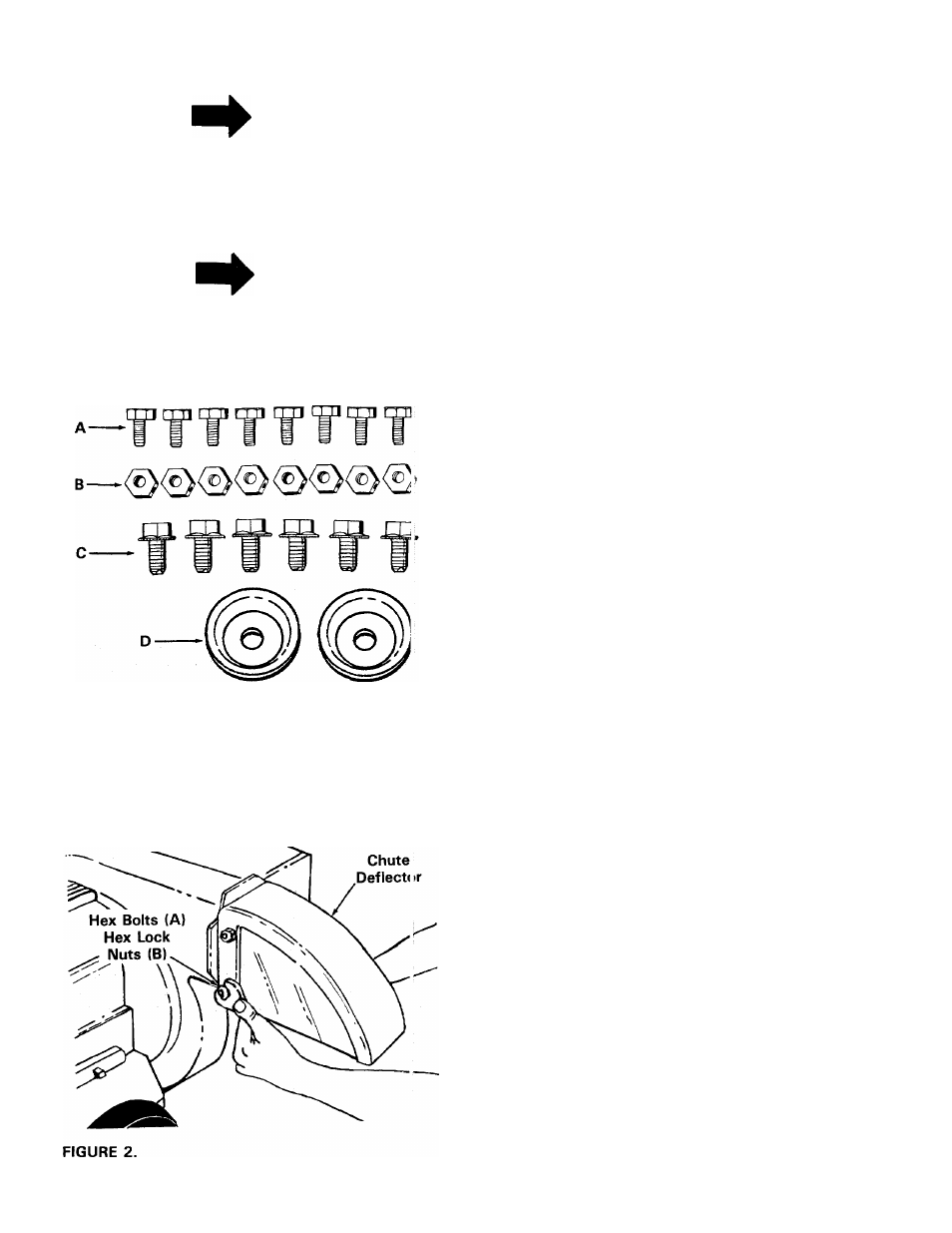
CHUTE DEFLECTOR INSTALLATION
1.
Place the chute deflector in position on the
discharge opening (on the left side of the shred-
---- der). See figure 2.
2. Secure chute deflector to discharge opening with
hex bolts (A) and hex lock nuts (B). Heads of the
hex bolts are inside the discharge opening. Hex nuts
go on the outsida
3. Tighten ail four nuts and bolts securely.