Assembly instructions – MTD 112-020A User Manual
Page 4
Attention! The text in this document has been recognized automatically. To view the original document, you can use the "Original mode".
A
В -
li I .!■
o-j
> 4
Г'
’
’ B-
ASSEMBLY INSTRUCTIONS
NOTE
-y
\/
G
FIGURE 1.
//'
'/
FIGURE 2.
This unit is shipped WITHOUT GAS
OLINE or OIL, After assembly, see
engine manual for proper fuel and
ertgine oU recommendations.
Tools Required for Assembly:
{1) Adjustable Wrench
7/16" Open End or Box Wrench
(1) 3/4" Open End or Box Wrench
-Contents of Hardware Pack: (See Figuie 1)
A (5) Hex Bolts 1/4-20 x 1 Va" Long {020 Only)
(6)
Hex Bolts
1/4-20 X 11/2"
Long (011 Only)
В (6) Hex Lock Nuts У4-20 Thread
C (1) Hex Bolt 1/4-20 X 13/4" Long (020 Only)
D (2) Cable Ties (020 Only)
E (4) Shoulder Bolts (Axles)
F (4) Belleville Washers
G (2) Hairpin Cotters
H (2) Hand Grips (Not Shown)
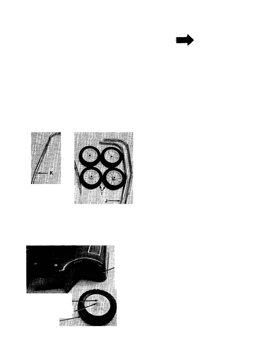
-Loose Parts In Carton: (See Figure 2)
I (4) Wheels
J (2) Upper Handles
К (1) Lower Handle
1. Remove lawn mower and all parts from the
carton. Make certain that all loose parts and
literature have been removed before the car
ton is discarded.
2.
Model 020 Only—Extend throttle control
assembly which is attached to engine at the
rear of the mower and place on floor. Be
careful not to bend or kink control wire.
Four
Cutting
Heights
Shoulder Bolt (E)
Belleville Washer (F)
Wheel (I)
FIGURE 3.
3. Your mower has four height settings. Use the
same hole for all four wheels when assem-
—bling. See figure 3.
A. Place shoulder bolt (E) through wheel (I).
See figure 3.
B. Place crown side of belleville washer (F)
towards the wheel (away from deck). See
figure 3.
C. Secure wheel to deck, using a 3/4" wrench.