MTD 24604C User Manual
Page 6
Attention! The text in this document has been recognized automatically. To view the original document, you can use the "Original mode".
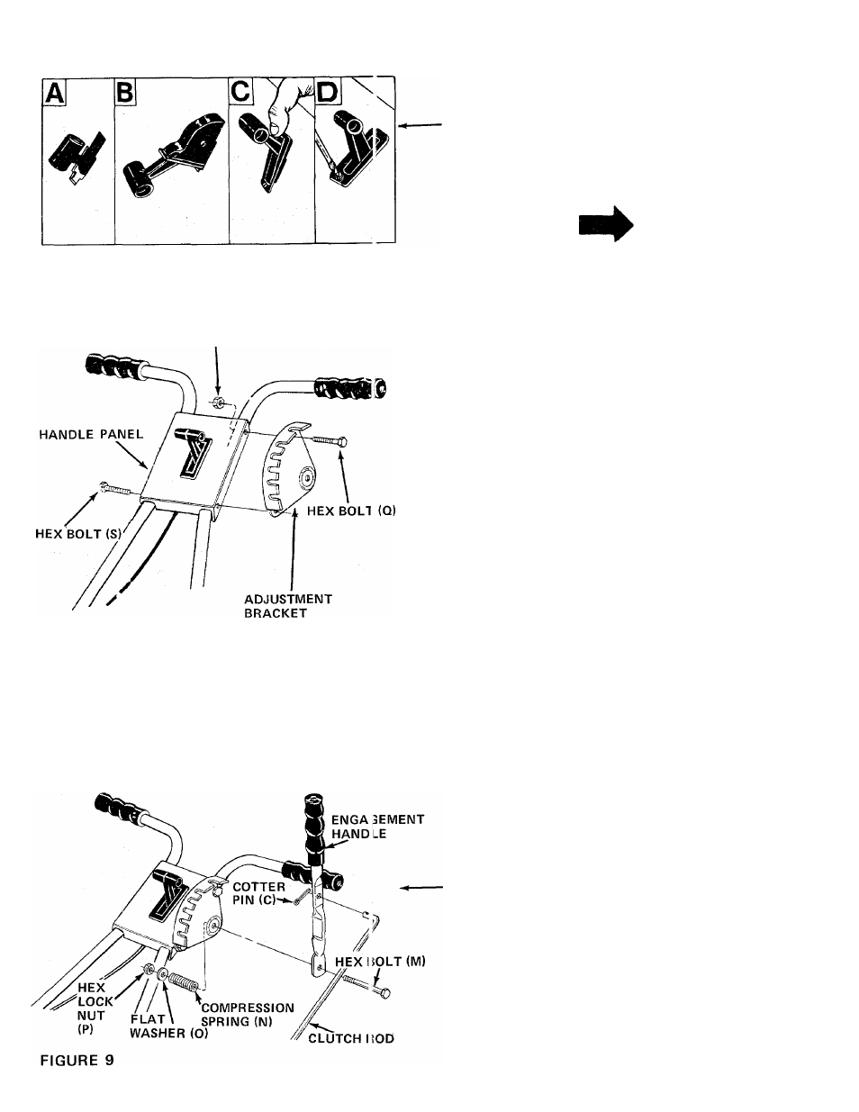
FIGURE 7
HEX LOCK NUT (R)
8. Assemble the throttle control to the handle panel
as follows.
A.
Hold the throttle control assembly beneath
the handle panel. Turn the control sideways
and insert the lever up through the wide
portion of the slot on the handle panel. See
figure 7A.
B. After the end of the lever is through the slot,
turn and then tip the control forward as shown
in figure 7B to slide it through the slot.
NOTE
The lever must be all the way to the
back of the control housing as shown
in figure 7B.
.
10
.
C.
D.
Push the control back into the slot in the
handle panel and press in place. Be certain the
control is locked securely into the slot. See
figure 7C.
Secure the throttle control to the handle panel
using self-tapping screw (U). See figure 7D.
11
.
12
.
FIGURE 8
Place the handle panel over the upper handles and
line up the holes. See figure 8.
Secure the right hand side of handle panel with
two one-inch long hex bolts (S) and hex lock nuts
(R). Do not tighten.
Secure the adjustment bracket to the left hand
side of handle panel with 1-1/4 inch long hex
bolts (Q) and hex lock nuts (R). See figure 8.
Now tighten securely all four bolts and nuts at
handle panel and four bolts and nuts at lower
handle.
13.
Place hex bolt (M) through bottom hole in
engagement handle as shown in figure 9, then
through hole in adjustment bracket.
14. Secure hex bolt with compression spring (N), flat
washer (0) and hex lock nut (P) on the inside of
of the adjustment bracket.
15. Secure bent end of clutch rod half to engagement
handle with cotter pin (C). See figure 9.