Assembly – MTD 240-623-003 User Manual
Page 5
Attention! The text in this document has been recognized automatically. To view the original document, you can use the "Original mode".
IMPORTANT
This unit has been shipped without
gasoline or oil in the engine. After
assembly, refer to separate engine
manual for proper fuel and engine oil
information.
Engine and
Pump Assembly
Reservoir
Tank Assembly Beam Support/
I
Latch Bracket
-Hitch
Assembly Tongue Assembly
FIGURE 1.
ASSEMBLY
UNPACKING
Remove the log splitter parts from the carton by cut
ting the corners of the carton. Make certain all parts
and literature have been removed from the carton
before the carton is discarded.
All hardware for assembly of the log splitter has been
placed in position on the various parts.
~Parts in Carton (See figure 1)
Reservoir Tank Assembly
Engine and Pump Assembly (Bolted to bottom of
carton)
Tongue Assembly
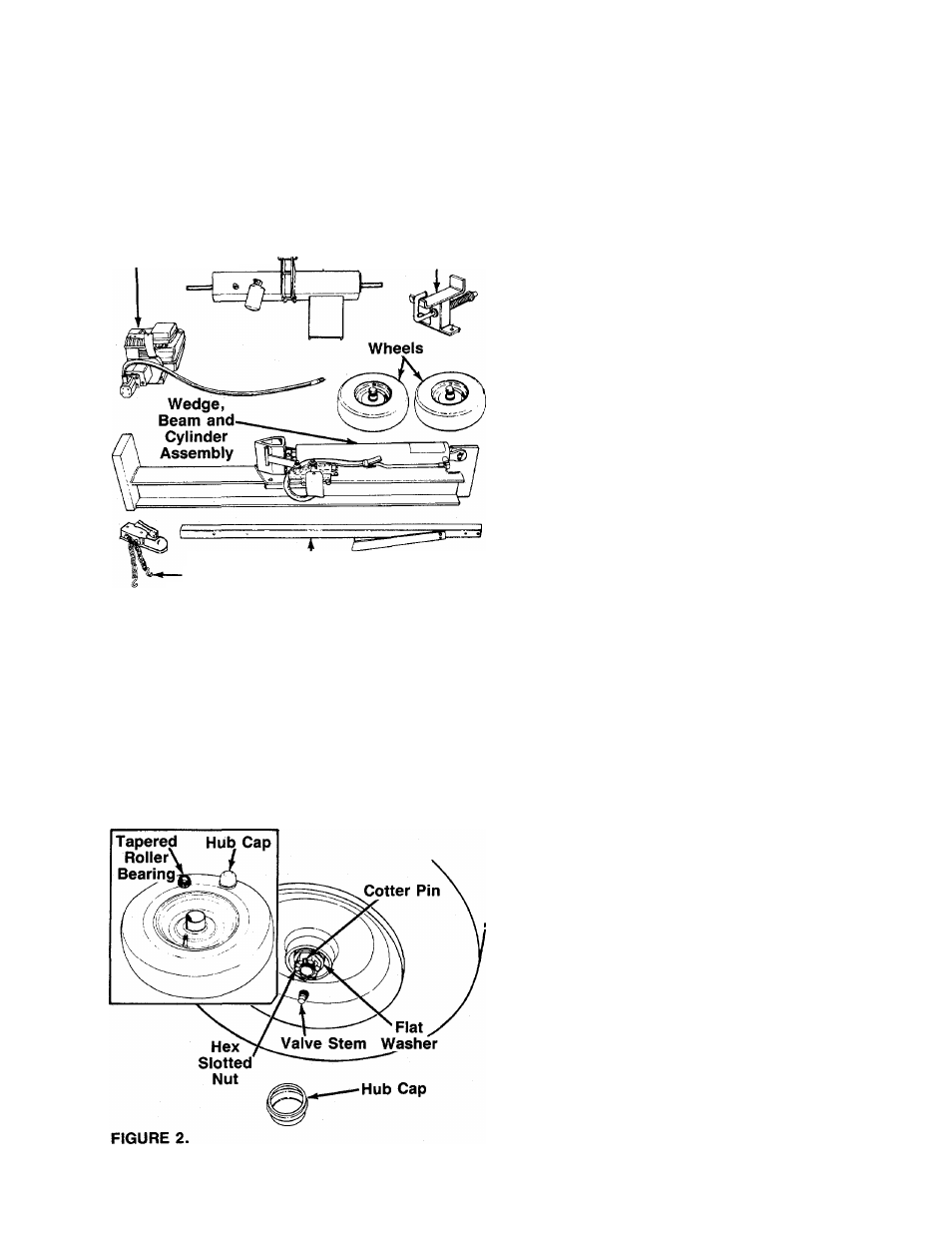
Wedge, Beam and Cylinder Assembly
Hitch Assembly
Wheels
Fenders (Not Shown—Model 424/LCD/22 Only)
Tools Required for Assembly
(1) Rubber Mallet or Plastic Hammer
(2) 9/16" Wrenches*
(2) 1/2" Wrenches*
(1) Adjustable Wrench
(1) Screwdriver
*Adjustable Wrenches may be used.
Other Materials Required for Assembiy:
Engine Oil
Unleaded Gasoline (regular grade gasoline is an
acceptable substitute)
Approximately 7.6 Gallons of Dexron II Automatic
Transmission Fluid or 10W Non-Foaming Hydraulic
Fluid
INSTALLATION OF WHEELS
Attach the wheels to the reservoir tank as follows. See
figure 2.
1. Pry off the hub caps which are attached to the
wheels. Remove one tapered roller bearing from
inside each wheel. See inset.
2. Remove the cotter pin, hex slotted nut and flat
washer from each axle.
3. Place one wheel on each axle, with the valve stem
facing outward.
4. Pack the tapered roller bearings with wheel bear
ing grease, and place one on each axle.
—5. Place one flat washer removed in step 2 on each
axle. Secure with hex slotted nut. Tighten sloted
nut until snug, then back off approximately 1/3 turn
or until one of the slots on the slotted nut lines up
with the hole in the axle.
6. Check the assembly of the wheels. There should
be no side to side play, and the wheel should spin
freely.
7. Place hub caps in position on wheels and tap on
with a rubber mallet or plastic hammer.