To replace mower blade drive belt (see fig. 25), T "i, To adjust brake (see fig. 26 – Poulan 157257 User Manual
Page 20
Attention! The text in this document has been recognized automatically. To view the original document, you can use the "Original mode".
S f R t / r F
à m ì
FRONT-TC
IMPORTAh
y u 1= p o i L
NECESSAFW
EQUALLY Si
S
ide
,
To obtain the
should be adji
1/2" lower tha
-BACK ADJUfc) FMtNT
T: DECK MUST BE LE\
) WIN G F Ft O N T - r O - B A
Y, BE SURE TO ADJUS^
SO MOY/ER WILL S'
50 I
cuttir
V E L S I D E - T O
lower housinci
wr
III
J| II !)/■ I ! I
the iTiower is m
ly I/S' to
highest
position.
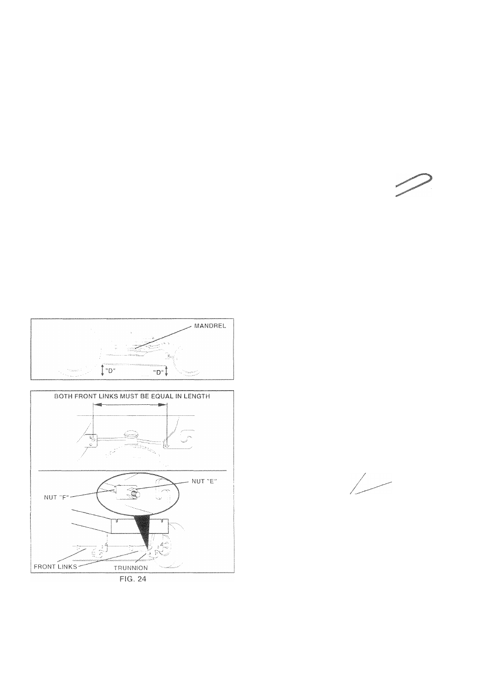
Check adjustment on right side of tractor. Measure dis
tance “D” directly in front and behind the mandrel at bottom
edge of mower housing as shown.
•
Before making any necessary adjustments, check that
both front links are equal in length. Both links should
be approximiately 10-3/8".
« If links are not equal in length, adjust one link to same
length as other link.
» To lower front of mower loosen nut “E” on both front
links an equal number of turns.
•
When distance “D” is 1/8" to 1/2" lower at front than
rear, tighten nuts “F" against trunnion on both front
links.
•
T
0 raise front of mower, loosen nut “F” from trunnion on
both front links. Tighten nut “E" on both front links an
equal number of turns.
•
When distance “D” is 1/8" to 1/2"
l o w e r a t
front than
rear, tighten nut “F” againsttrunnion on both front links.
•
Recheck side-to-side adjustment.
FIG. 23
TO REPLACE MOWER BLADE DRIVE BELT
(See
Fig.
25)
The miower Diade drive Delt may De replaced without tools
Park the iracfor on level suriace. Engage parking brake.
! U
YlOWEt
A/crk be
BE
guu
removal
)wer in reverse ore
'e rnov
a
11 ns t njct i o n s.
MANDBCL
RJLLiW T
IDLER
P'L . EYS
T "i
MANDREL PULLEY
FIG. 25
TO ADJUST BRAKE (See Fig. 26|
Your tractor is equipped with an adjustable brake system
which is mounted on the side of the transaxle.
If tractor requires more than six (6) feet stopping distance
at high speed m highest gear, then brake must be adjusted.
•
Depress dutch./brake pedal and engage parking brake.
•
Measure distance between brake operating arm and
nut “A” on brake rod.
•
If distance is otherthan 1 -1/2", loosen jam nut and turn
nut “A” until distance becomes 1-1/2". Retighten jam
nut against nut "A”.
•
Readiest tractorfor proper stopping distance as stated
above. Readiest if necessary. If stopping distance is
still greater than six (6)
f e e t
in highest gear, further
maintenance is necessary. Contact your nearest au
thorized service center/department.
WITH
PARKING
BRAKE
"ENGAGED”
NUT"A”
. JAM
NUT
\
imi
• OPERATING
ARM
/
DO NOT TOUCH THIS NUT, IF FURTHER BRAKE ADJUST
MENT IS NECESSARY CONTACT YOUR NEAREST AUTHO
RIZED
SERVICE CENTER/DEPARTMENT
20
FIG,
26