Chapter 5 – Asus PM17TU User Manual
Page 12
Attention! The text in this document has been recognized automatically. To view the original document, you can use the "Original mode".
Chapter 5
2. PM17T/PM17TS
Technical Information
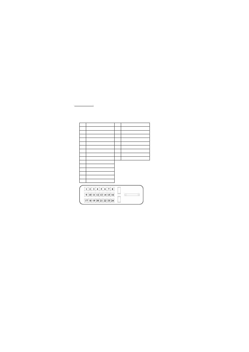
PIN
Signal (DVI)
PIN
Signal (DVI)
1
TMDS Data 2-
16
Hot Plug Detect
2
TMDS Data 2+
17
TMDS Data 0-
3
TMDS Data 2/4 shield
18
TMDS Data 0+
4
TMDS Data 4-
19
TMDS Data 0/5 shield
5
TMDS Data 4+
20
TMDS Data 5-
6
DDC Clock
21
TMDS Data 5+
7
DDC Data
22
Clock shield
8
Analog Vertical Synchronal
23
Clock +
9
TMDS Data 1-
24
Clock -
10
TMDS Data 1+
11
TMDS Data 1/3 shield
12
TMDS Data 3-
13
TMDS Data 3+
14
+5V Power
15
Ground
5.2 Visual Inspection
Even the normal pixels on the LCD screen reach 99.99% or higher, there
maybe0.01%orlesspixelsshowingdark or light while displaying.
This manual is related to the following products: