Assembly, Attaching the bar & chain, Chain brake & ска angle – Husqvarna 23 COMPACT User Manual
Page 5: Warning, A warning, Computed kickback angle (cka) table
Attention! The text in this document has been recognized automatically. To view the original document, you can use the "Original mode".
CHAIN BRAKE & СКА ANGLE
Ik
WARNING:
The effectiveness of a
chain brake in reducing operator injuries
has not yet been fully determined. We can
not represent that a chain brake is an effec
tive safety device to prevent or reduce the
hazard of injuries resulting from kickback.
DO
NOT
ASSUME
THAT
THE
CHAIN
BRAKE WILL PROTECT YOU IN THE
EVENT OF A KICKBACK. Instead, use
the saw properly and carefully to avoid kick
back. Reduced-Kickback bars and Low-
Kickback chains reduce the hazard of kick
back and are recommended. Repairs on a
chain brake should be made by an Autho
rized Service Dealer.
A WARNING:
Computed
kickback
angle (CKA) listed on your saw and listed in
the CKA table below represents angle of
Computed kickback angle (CKA) Table
kickback your bar and chain combinations
will have when tested in accordance with
CSA and ANSI standards. When purchas
ing replacement bar and chain, consider
ations should be given to the lower CKA val
ues. Lower CKA values represent safer
angles to the user, higher values indicate
more angle and higher kick energies. Com
puted angles represented in the non-acti
vated column indicate total energy and
angle associated without activation of the
chain
brake
during
kickback.
Activated
angle represents chain stopping time rela
tive to activation angle of chain brake and
resulting kick angle of saw.
The following guide bar and chain com
binations meet kickback requirements of
CSA Z62.1, Z62.3, & ANSI B175.1 Use of
bar and chain combinations other than
those listed is not recommended and may
not meet the CKA requirements per stan
dard.
MODEL
BAR
CHAIN P/N
CKA without
chain brake
P/N
Length
23 Compact
5018540-52
14"
6081001-29
43.8“
NOTE: This saw complies with Federal
OSHA regulations for commercial logging.
SAFETY NOTICE: Exposure to vibrations
through
prolonged
use
of
gasoline
powered hand tools could cause blood
vessel or nen/e damage in the fingers,
hands, and joints of people prone to
circulation disorders or abriormal swellings.
Prolonged use in cold wéather has been
linked to blood vessel damage in otherwise
healthy people. If symptoms occur such ^
numbness, pain, loss of strength, change in
skin color or texture, or loss of feeling in the
fingers, hands, or joints, discontinue the
use of tfiis tool auid seek medical attention.
An
anti-vibration
system
does
not
guarantee
the
avoidance
of
these
problems. Users who operate power tools
on a continual and regular basis must
monitor closely their physical condition and
the condition of this tool.
SPECIAL NOTICE: Your saw is equipped
with a temperature limiting muffler and
spark arresting screen which meets the
requirements of California Codes 4442 and
4443. All U.S. forest land and the states of
California, Idaho, Maine, Minnesota, New
Jersey, Oregon, and Washington require
many internal combustion engines to be
equipped with a spark arrestor screen by
law. If /ou operate a chain saw where such
regulations
exist,
you
are
legally
responsible for maintaining these parts.
Failure to do so is a violation of the law.
Refer to SERVICE section.
If you need assistance, contact your Autho
rized Service Dealer or call the 1-800 num
ber listed on the back of this manual.
ASSEMBLY
Do not be alarmed by a rattle in your unit.
This is a normal sound from the fuel filter in
the empty fuel tank. You may also smell
i
asoline or see oil residue on the muffler.
his is normal from the testing and carbure
tor adjustment process while the unit was
manufactured.
A
WARNING:
Recheck each assembly
step if the saw is received assembled. A-
ways wear gloves when handling the chain.
The chain is sharp and can cut you even
when it is not moving!
ATTACHING THE BAR & CHAIN
(If not already attached)
• Loosen and remove ti^e bar clamp.
• Remove and recycle plastic shipping
spacer.
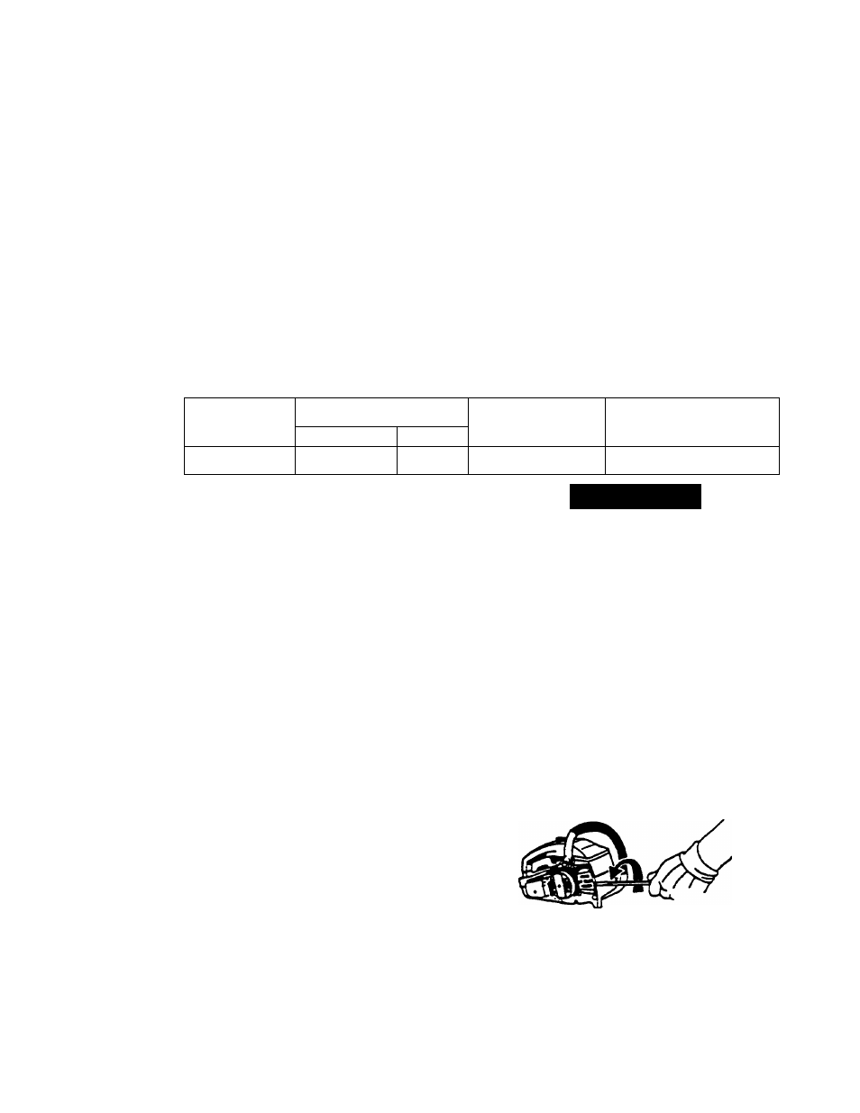
An adjusting pin and screw is used to ad
just the tension of the chain. It is very im
portant when assembling the bar, that the
pin located on the adjusting screw aligns
into a hole in the bar. Turning the screw
will move the adjustment pin up and
down ttie screw. Locate this adjustment
before you begin mounting the bar onto
the saw. See illustration below.