Gear case assembly 4500 – MTD 214-100A User Manual
Page 10
Attention! The text in this document has been recognized automatically. To view the original document, you can use the "Original mode".
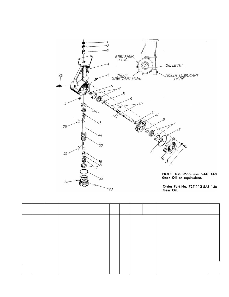
GEAR CASE ASSEMBLY 4500
M a i n t a i n w i t h f i v e ( 5 ) o u n c e s o f l u b r i c a n t .
PARTS LIST FOR GEAR CASE ASSEMBLY 4500
REF.
NO.
PART
NO.
COLOR
CODE
DESCRIPTION
NEW
PART
REF.
NO.
PART
NO.
COLOR
CODE
DESCRIPTION
NEW
PART
1
716-119
Snap Ring %" Dia. Shaft
14
710-371
Hex Scr. 5/16-18
X
.88" Lg.
2
721-100
Oil Seal %" Shaft
15
736-119
L-Wash. 5/16" Scr.*
3
748-106
Sleeve Bearing .752" I.D.
16
717-227
Bearing Cap—Bolton Type
4
717-226
Gear Case
17
741-107
Roller Bearing %" Bore
5
737-103
Sq. Hd. Pipe Plug
%"
Thd.
18
711-469
Spacer .755" I.D. x 1.265" O.D.
6
721-102
Oil Seal Double Lip 1" Shaft
19
738-171
Worm Shaft
7
741-108
Roller Bearing 1" Bore
20
717-167
Worm
8
711-131
Spacer 1.005" I.D. x 1.390"
21
716-101
Snap Ring for .750" Dia. Shaft
O.D.
22
735-100
O-Ring 2.12
X
2.38
9
711-133
Tine Shaft
23
714-474
Cotter Pin Vs" Dia. x .75" Lg.*
10
714-103
#91 Woodruff Key
V
4
" x
%"
24
10538
Bearing Adjustment Cap
Dia.
25
714-126
#9 Hi-Pro Key 3/16
X
%"
Dia.
11
716-102
Snap Ring for 1.00" Dia. Shaft
26
737-102
Sq. Hd. Pipe Plug \A/ith Vent
12
717-105
Worm Wheel
%"
Thd.
13
735-101
0-Ring 3.62 X 3.88
*For faster service, obtain standard nuts, bolts and washers locally. If these items cannot
be obtained locally, order by part number and size, as shown on parts list.
10