Spark plug, Cooling system, Tine removal and installation ^ warning – Troy-Bilt 12159 User Manual
Page 18: Maintenance/service, Warning
Attention! The text in this document has been recognized automatically. To view the original document, you can use the "Original mode".
MAINTENANCE/SERVICE
Spark Plug
Inspect spark plug annu
ally or every 75 operating
hours. Before inspect
ing, clean around the
plug. Then remove plug
to check the electrodes,
gap and porcelain jacket.
Figure 18: Set spark plug
electrode gap at .030".
Use a wire feeler gauge to be
sure the gap is .030“. If replacing the plug, use a Cham
pion CJ-6Y or equivalent.
Cooling System
It is important to frequently check for, and remove, all
grass clippings, dirt and other debris that may accumu
late on the engine: around the cooling fins; on the air in
take screen; and on levers and linkage. This helps to
ensure adequate air cooling and correct engine speed.
TINE REMOVAL AND INSTALLATION
^ WARNING
Avoid contact with the cutting edges on the tines.
To avoid personal injury when removing or in
stalling tines, wear heavy work gloves. The engine
must be off, all moving parts completely stopped,
and the spark plug wire disconnected from the
spark plug and moved away from the plug.
Knowing how to remove and reinstall the tine sections
will help you accomplish the following tine configura
tions: a) to change from the standard 9" tilling width to a
narrower 6" tilling width for smaller areas; b) to swap the
positions of the two inner tine sections to adapt to very
stony soil conditions; c) to replace damaged or badly
worn tine sections. IMPORTANT: The ring lock pin (A,
Figure 19) is under spring tension -- wear gioves
when removing or replacing the ring lock pin to pro
tect your fingers.
To Create a Narrow 6" Wide Tilling Width:
•
For easy tine access, prop the machine forward care
fully so it rests on the front of the tubular carrying handle.
The work surface should be flat and firm.
• Flip open the ring (A, Figure 19) on the ring lock pin
that secures either the left or right side tine sections.
Pull the ring lock pin out of the tine shaft.
• Slide the outer tine section off the tine shaft and mark
it as to which side it is from (left or right) and whether it’s
an outer or inner tine section.
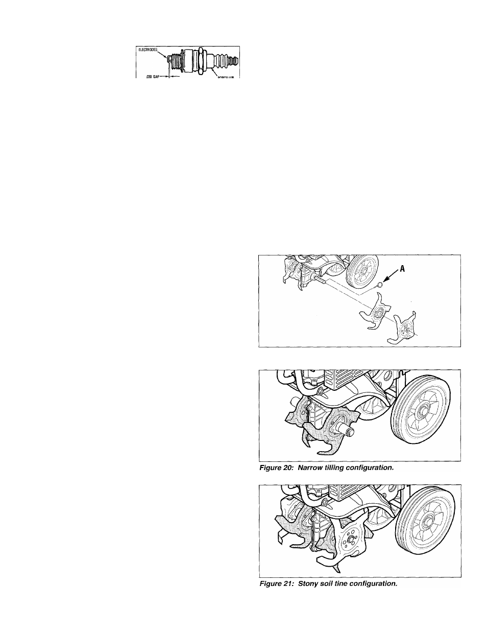
• Keep the inner tine section on for a 6" wide tilling swath
and then add one of the long bushings provided with the
unit. See Figure 20. Insert the ring lock pin through the
rounded side of the tine shaft and snap the ring down
over the shaft (see DETAIL, Figure 6, page 10).
• Repeat on the opposite side of the machine.
For Stony Soil Conditions, Configure Tines As Follows:
•
If tilling in stony soil, remove the ring lock pin (A, Figure
19) from both sides of the machine. Remove both outer
tine sections. Identify each section as a left or right side
tine and whether it is an inner or outer section.
• Remove the inner tine sections and swap their posi
tions (inner right-side section goes on left side of ma
chine, and vice-versa).
•
• Replace the two outer tine sections on the sides of the
machine from which they came. See Figure 21.
• Insert the ring lock pins through the rounded side of
the tine shafts and snap the ring down over the shafts
(see DETAIL, Figure 6, page 10).
To Replace Worn Tine Sections:
•
Remove the ring lock pin (A, Figure 19) from both
sides of the unit. Remove the old tine sections and re
place them with new tine sections. (The tines are too
worn if tilling takes much longer than before and soil is
not being mixed thoroughly enough.) Insert the ring lock
pins through the rounded side of the tine shafts and
snap the ring over the shaft (see DETAIL, Fig. 6, pg. 10).
Figure 19: Remove ring lock pin (A) to take off tines.
18