Optional tine positions, Warning, Laking border edges – Troy-Bilt 12159 User Manual
Page 15: Operation
Attention! The text in this document has been recognized automatically. To view the original document, you can use the "Original mode".
OPERATION
TIPS & TECHNIQUES
• Adjust engine speed to the tilling
conditions. The rotating tines help
to pull the machine forward. Use
slower engine speeds and a
shallow tine depth setting when
first learning to use the equip
ment and whenever you are till
ing on hard, rough or uneven
ground.
•
Regulating the amount of pres
sure applied to the handlebars
helps to control tilling depth. De
pending upon soil firmness and tex
ture, you may have to push down
or lift up on the handlebars to
achieve the correct tilling depth.
• Set the handlebars at a height
which gives you maximum control
at all times. Set your adjustment
so the machine feels comfortable
and well-balanced.
• If the machine stays and tills in
one spot, try swinging the handle
bars from side to side to start the
machine moving forward again.
Optional Tine Positions
Depending upon the tilling or culti
vating project to be done, you have a
choice of three tine patterns:
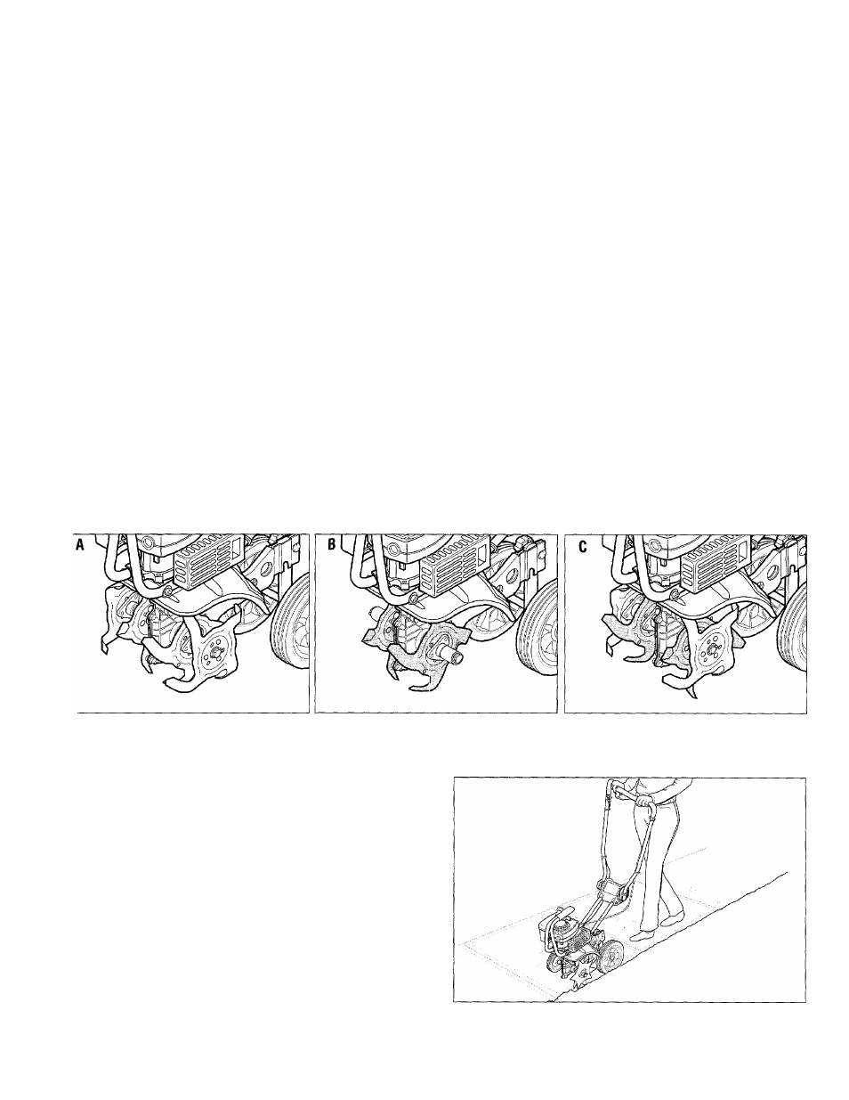
Wide Tine Pattern-
Your unit, as
shipped from the factory, is set up for
general tilling and cultivating. This
tine pattern employs all four tine sec
tions arranged as shown in Figure
15, “A”. This pattern provides the
widest possible tilling width - 9".
Narrow Tine Pattern-
To obtain a
narrower tilling width (6"), remove
the outside tine section on the left-
and right-sides of the unit. This pat
tern is shown below in Figure 15,
“B”. It’s great for flower beds. The
tine removal procedure is explained
in the ’’Maintenance/Repairs”
section.
WARNING
Contact with rotating tines will
cause serious personal injury.
Before attempting to remove or
clean tines, stop the engine,
let all moving parts stop com
pletely, then disconnect spark
plug wire and move wire away
from plug.
Stony Soil Tine Pattern-
When
tilling deeply in stony soil, stones
may jam frequently between the in
ner tines and the machine hood. To
minimize this, swap the positions of
the two inner tine sections. Refer to
Figure 15, “C”. The procedure for
swapping the tine positions is ex
plained in the “Maintenance/Repairs”
section.
igure 15: “A” shows all four tine gangs in standard position; “B” shows two outer gangs removed for narrow tilling;
hows the two Inner gangs have been swapped for stony tilling conditions.
lAKING BORDER EDGES
aking clean, sharp edges next to walkways, driveways,
Jths, planted areas, patios, etc., with your Edger At-
chment is easily accomplished. Refer to page 10 in
is manual for instructions on attaching this accessory.
sually the edger blade is mounted on the right side for
right-handed person and on the left side for a left-
inded person.
ke your time when creating an edge along a walkway
path or drive. Decide how far away the edge is going
be from the walk or drive, then slowly proceed using
3 walk or drive as your sight line.
te built-in maneuverability of the equipment helps you
5ate a near-perfect circle, or to negotiate a meander-
) or abruptly-changing path.
Figure ISA: Make sharp, clean edges with the
Border/Edger A ttachment.
15