Securing the cable (hardware d), Installation of wheels (hardware e) – MTD 030 thru 062 User Manual
Page 9
Attention! The text in this document has been recognized automatically. To view the original document, you can use the "Original mode".
End of
Control
Handle
Hex Lock
Nut
Truss
Machine
Screw
FIGURE 8.
Smaller Cupped
Front Wheel Washer
Use These Holes
For Front Wheel
4. Holding the control box near the left side of the upper
handle (control box must be inside the handle), hook the
“Z” end of the brake cable into the control handle from
the outside to the inside. See figures 7 and 8.
5. Place the control box on the upper handle just below
(touching) the end of the control handle as shown in
— figure 8. Secure with hardware removed in step one by
placing hex lock nut into the indent on the inside of the
control box. Screw the truss machine screw into the hex
lock nut.
A
SECURING THE CABLE (Hardware D)
Secure the cable to the left side of the handle as follows.
WARNING: When attaching the control cable,
the cable must be routed to avoid contact with
all sharp edges and hot surfaces to prevent
damage to the cable, which will render the con
trols inoperative.
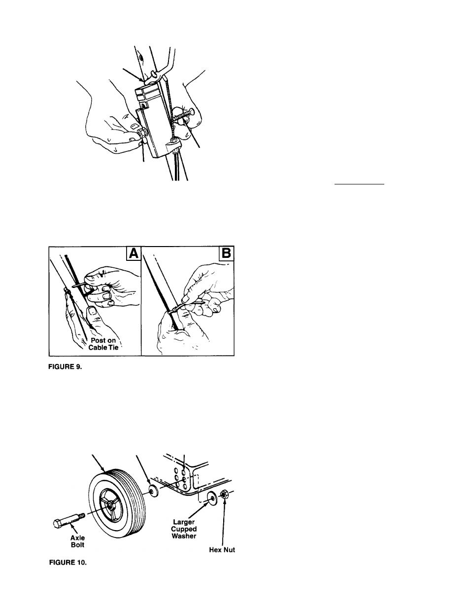
1. Insert posts on cable ties into holes provided on the
inside of the handle, one on the upper handle and two on
the lower handle. The holes may be either on the inside
— or outside of the handles. See figure 9A.
2. Secure the cable with the cable ties. See figure 9B. Trim
excess ends of cable ties.
INSTALLATION OF WHEELS (Hardware E)
The three holes provide three cutting heights for your mower.
Use the same hole location for all four wheels when
assembling. If wheels are to be assembled in the lowest cut
ting position (highest hole in the deck), refer to the note
below.
If your mower has two sets of holes (see figure 10), the front
wheels must be assembled in one of the three holes nearest
the front of the deck. The rear wheels must be assembled in
one of the three holes nearest the rear of the deck.
To assemble the wheels: (See figure 10)
1. Block up the mower securely.
2. Place axle bolt through wheel. (Hub side of wheel must
face deck.)
- 3. Place one smaller cupped washer on axle bolt, with the
cupped side of washer toward the deck (away from
wheel).
NOTE:
If the lowest cutting position (highest hole in the deck)
is used, it is necessary to place the larger washer on the out
side of the deck and the smaller washer on the inside.
4. Secure wheel to deck with one larger cupped washer on
the inside of the deck (cupped side against the deck) and
hex nut. Tighten securely.
5. Assemble the other wheels in the same manner.
Remove the blocks.