Unpacking, To remove unit from carton, Tools required for assembly – MTD 030 thru 062 User Manual
Page 7: Disconnect spark plug wire, Assembly instructions, Attaching the lower handle (hardware a)
Attention! The text in this document has been recognized automatically. To view the original document, you can use the "Original mode".
UNPACKING
TO REMOVE UNIT FROM CARTON
1. Remove staples, break glue on top flaps, or cut tape at
carton end and peel along top flap to open carton.
2. Remove loose parts if included with unit (i.e., owner’s
manual, etc.).
3. Cut along dotted lines and lay carton down flat.
4. Remove packing material.
5. Slide unit out of carton. Check carton thoroughly for
loose parts.
TOOLS REQUIRED FOR ASSEMBLY
(1) 1/2" Wrench
(2) 9/16" Wrenches
(1) Phillips Screwdriver
(1) 3/4" or Adjustable Wrench
(Two 6" Adjustable Wrenches may be used instead of the
above.)
DISCONNECT SPARK PLUG WIRE
Before setting up your lawn mower, disconnect the spark
plug wire from the spark plug, and ground it against the
engine. See figure 4.
Spark
Plug
^ “V”Slot ^
on Engine \
Spark
Plug
Wire
Briggs & Stratton Engines
Retaining
Post
Spark
Piug
Spark Piug Wire
Tecumseh Engines
FIGURE 4.—Grounding the Spark Piug Wire
ASSEMBLY INSTRUCTIONS
IMPORTANT; This unit is shipped WITHOUT GASOLINE
or OIL. After assembly, service engine with gasoline and
oil as instructed in the separate engine manual packed
with your unit.
NOTE:
Reference to right or left hand side of the mower is
observed from the operating position.
This owner’s guide covers various models of mowers.
Follow only the instructions which pertain to your unit.
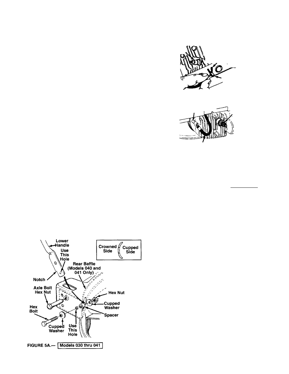
Cupped Washer
ATTACHING THE LOWER HANDLE (Hardware A)
Models 030 thru 041 only:
1. Raise the rear of the deck and block securely.
2. Model Series 040 only: Place the rear baffle in position
inside the rear of the deck. Use one axle bolt and hex nut
on each side of the rear of the deck to secure baffle
temporarily so you can attach the lower handle. See
figure 5A.
NOTE;
Remove axle bolt and nut when assembling the
wheels, page 9.
3. Place one cupped washer on each hex bolt 1-1/2" long
(crowned side of washer goes against the head of the
hex bolt).
4. Insert the ends of the lower handle through the slots in
the rear of the deck.
NOTE:
It is helpful to have another person hold the handle in
position as you continue.
5. Place one spacer between the bottom hole in lower
handle and forward hole in deck (model 030 series) or
— baffle (model 040 series). See figure 5A. Use a screw
driver to pry the handle away from the deck or baffle if
necessary.
6. Using a screwdriver, line up the forward hole in the deck
or baffle, the spacer and the bottom hole in the handle,
then insert hex bolt as shown from the outside of the
deck.
7. Secure with cupped washer (cupped side against the
handle) and hex lock nut. Do not tighten at this time.
8. Repeat steps 5 through 7 to attach the other side of the
handle.
9. Tighten both hex bolts and nuts securely.