Fs^i, S Page 12: Ji^s(2)a<3№fflig&. mw^fs&ns.mz.^n, Aissg(2)ii's-, s, I'j^if>te±, jf, ssctti, Ffl h?£fs ft ieii-m'i
Page 12: Ji^s(2)a<3№fflig&. mw^fs&ns.mz.^n, Aissg(2)ii's-, s, I'j^if>te±, jf, ssctti, Ffl h?£fs ft ieii-m'i
Attention! The text in this document has been recognized automatically. To view the original document, you can use the "Original mode".
6.
n)
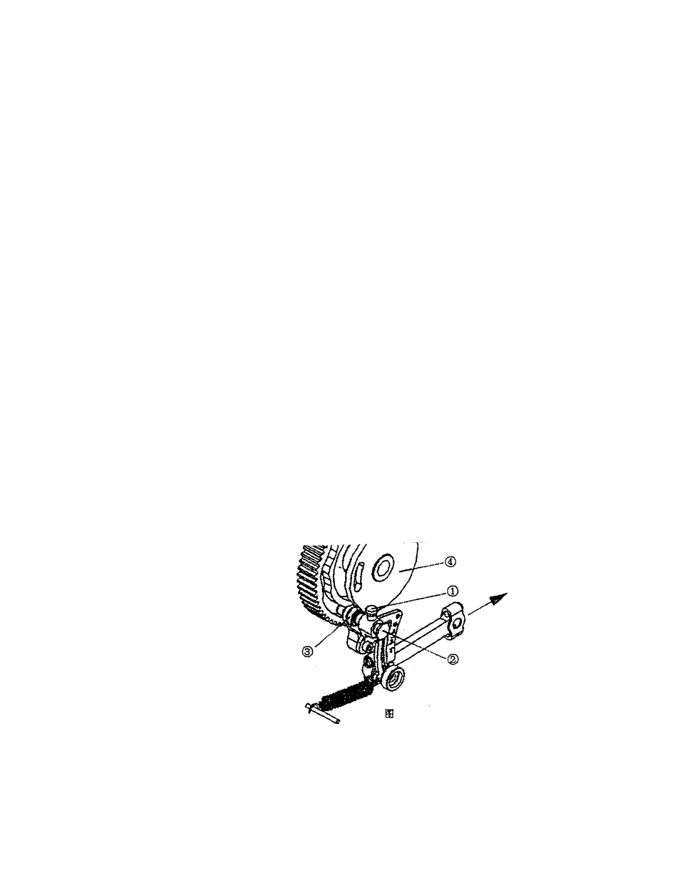
itSB 13
-fs^i
^s fs, '±m.mn^%9r, ji^^iSiP^pfl, eiis±m#rts ji^s(2)a<3№fflig&. mw^fs&ns.mz.^n, ^aissg(2)ii's-, s №’1. i'j^if>te±, jf, ssctti^ ffl h?£fS ft iEii-M'i' . #ia®. $ d b i 4 M ^ . 7. Fxmction of thread trimming. The button clamp-lifting rod will drive the crank of thread trimming shaft, and the motion of thread trimmer will cut inside thread. Adjust the position of hanger crank(P25-i.5B4), make thread trimmer cut thread first, then lift button clamp. Or if the button clamp is lifting while the trimming knife fails to reach the trimming position, the thread will break and the stitches easily tend to loose. 7 . 8. Shift cam unit, (model 1375A3) Open the hinged cover, you can see the shift cam unit (as shown in Figl5), which is designed for model 1375A3, and is used to shift crossover stitches and parallel stitches. The position which the illustration shows is suitable to crossover stitches. If you need parallel stitches, you can loose screw (1), pull out the handle (2), make the wheel (3) well touch with profile of the shift cam, and then tight the 15 Fig-15 - 10 -