Lincoln LN-7 User Manual
Page 9
Attention! The text in this document has been recognized automatically. To view the original document, you can use the "Original mode".
The Lincoln Electric Company
Cleveland, Ohio 44117
Assembly and Installation
SEC. J2.3 ELEaRICAL INSTALLATION
Sec. J2.3.1
Input Cable: LN-7 to Power Source
The input cable between the wire feeder and the power
source consists of a four-conductor control cable and an
electrode cable. The control cable has lugged leads on the
power source end and a polarized plug on the wire feeder
end. With the power source turned off, install the input
cable per the following instructions:
i
I. Connect the end of the control cable with the lugged
‘.-leads to a constant voltage type power source. For
Lincoln power sources follow exactly thé instructions
(including all jumpers on the power source terminai
strips) for the specific power source per the wiring
diagrams in Sec. J2.3.2.
2. For constant voltage power sources not included in Sec.
J2.3.2, request a copy of Sec. J2.3.3 for connection
instructions.
3. If input cables longer than the standard length (available
as 7, 25, 50, 75 and 100’ lengths) must be used, 50’
K-177 extension cables can be installed. These have
polarized plugs on each end of the control cable and a
4/0 electrode cable. Install the extensions between the
standard input cable and the wire feeder. Total input
lead length should not exceed 400’. When using the
longer lengths of extension cables, it may be necessary
to add parallel electrode cables to limit the voltage drop
in the cable.
4. Loosen the screws holding the clamp to the rear vertical
support of the wire feeder frame. Put only the electrode
cable under the clamp.
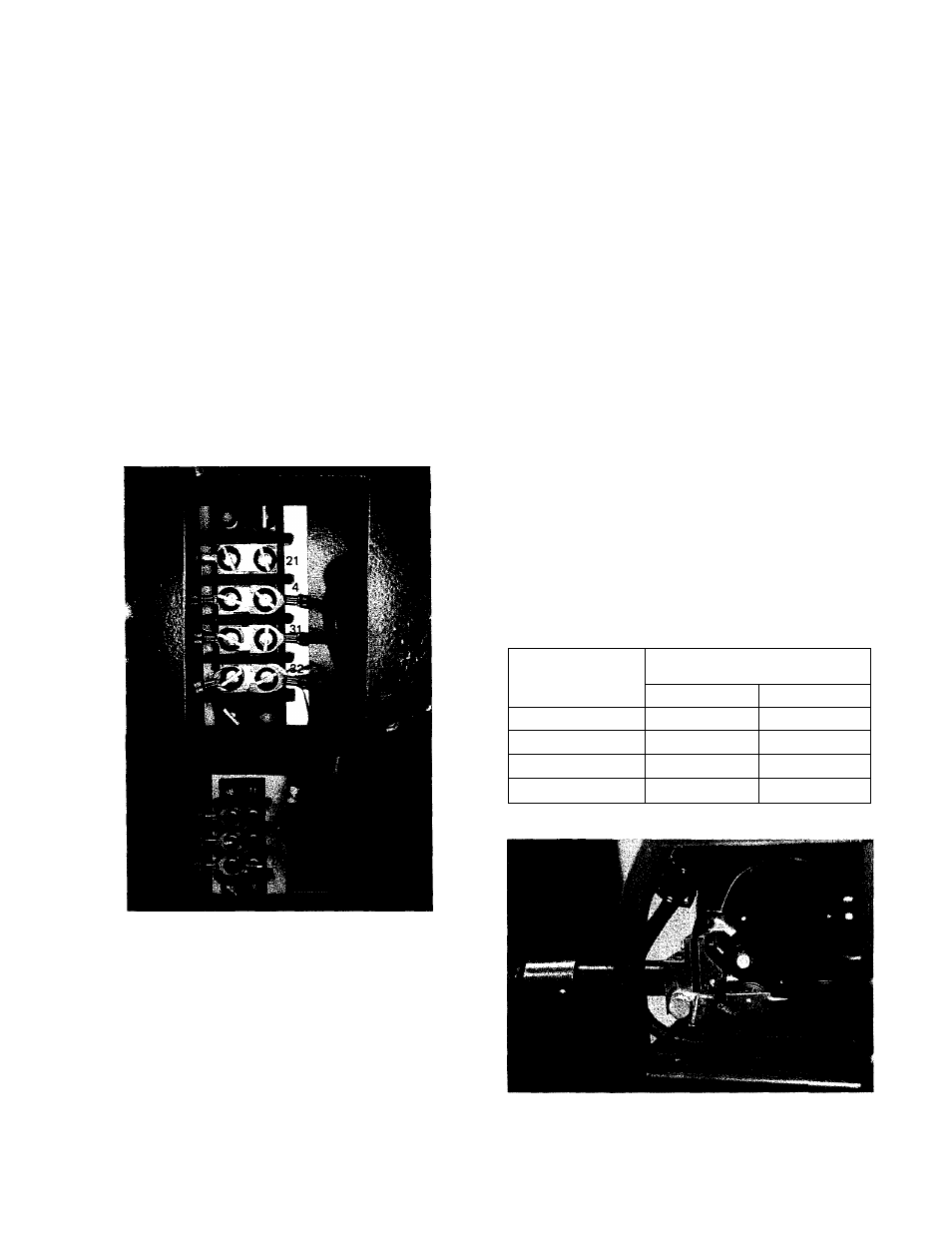
5. Coimect the end of the electrode cable to the end of the
brass block on the wire feeder using the bolt provided.
Be sure the cable is placed to allow easy access to the
drive roll and guide tube screws. (See photo below.)
Tighten the screws on the electrode cable clamp.
6. Run the control cable under the wire feed motor and
insert the plug into the mating receptacle below the
LN-7 nameplate.
7. Connect a ground lead of sufficient size and length (per
the following table) between the To Work’ stud on the
power source and the work. Be sure the connection to
the work makes tight metal-to-metal contact.
Current
Amps
60% Duty Cycle
Copper Ground Cable Length
Up to 50'
50' - 100'
300
0
00
400
00
000
500
00
000
600
000
0000
September 1976
-9-