Lincoln LN-7 User Manual
Page 7
Attention! The text in this document has been recognized automatically. To view the original document, you can use the "Original mode".
The Lincoln Electric Company
Cleveland, Ohio 44117
Assembly and Installation
f ^
SEC.J2.2 MECHANICAL INSTALLATION
Sec. J2.2.1
Wire Feed Unit and Wire Reel
The LN-7 is shipped ready to install in the work
location.
September 1971
Sec. J2.2.2
Wire Feed Rolls and Guide Tubes
NOTE: The maximum sizes the LN-7 will satisfactorily
feed are 7/64” Innershield® and 3/32” solid electrodes.
The drive roll, idle roll and guide tubes for the electrode
size specified on the order is shipped with the wire feed
unit. The electrode sizes that can be fed with each roll and
guide tube are stenciled on each part. Instructions to install
these parts on new machines or replace them on used
machines, are as follows;
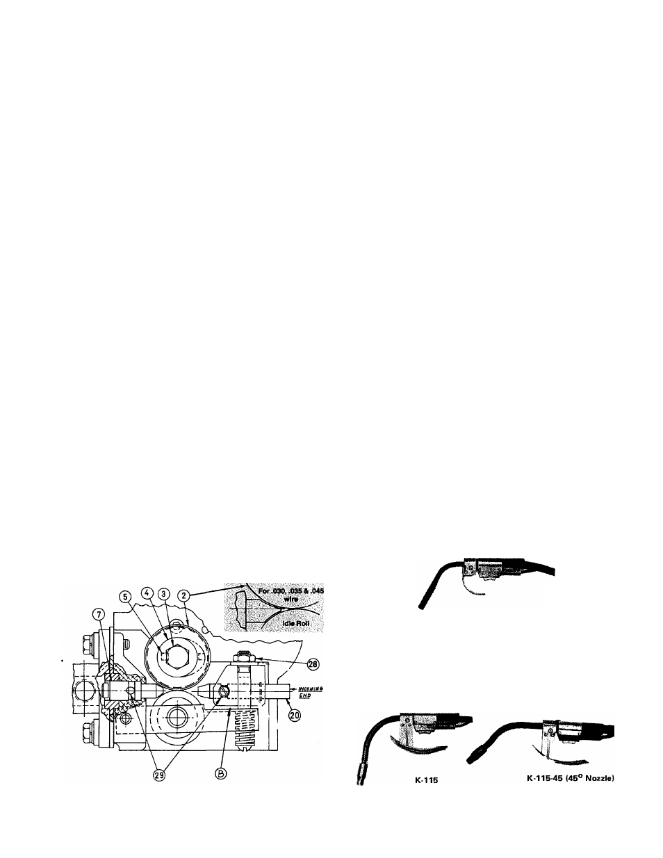
A. Loosen the idle roll tension nut (item 28) approximately
3 full turns or use a screwdriver to pry the idle roll arm
down at point B .
B. Remove hex head screw (item 3) & the drive roll clamp
ing collar (item 4). (On new machines remove the tape &
drive roll key from the collar.) Insert the key (item 5)
into the keyway of the output shaft.
C. Wipe the drive roll & spacer surfaces clean. Install one
drive roll (item 2), then the spacer & the second drive
roll. (For .030, .035 & .045 electrode, the drive roll
is one piece. For '/i6 electrode there is no spacer).
D. Install drive roll clkmping collar & hex head screw pre
viously removed. Tighten hex head screw securely.
E. Back out the two guide tube clamping set screws (item
29).
F. Insert the outgoing guide (item 7) (the one with the plas
tic insert) into the front hole. The guide tube for .030",
.035" and .045" wire has a non-symetrical chisel end.
Be certain the contour with the larger radius and the
exposed oval opening for the wire faces the grooved
drive roll. Push the guide tube back as far as it will
go and tighten the clamping set crew. Insert the incom
ing guide tube (item 20) into the rear hole as far as
it will go and tighten the clamping set screw. These
set screws are dog point. When the two tubes are instal
led properly these dog points will lock into the annular
groves that are in each of the guide tubes,
G. Tighten the idle roll tension nut (item 28) or remove the
screwdriver used as a wedge in step A. The tension nut
should normally be tightened until it bottoms for wire
sizes 1/16” and larger. For smaller wire sizes and alumi
num wire the tension nut should be loosened if the wire
tends to buckle in the guide tube, cable or between the
drive rolls and outgoing guide tube.
H. To change drive rolls and guide tubes for a different size,
reverse the above procedure.
September 1976
Sec. J2.2.3
Gun & Gun Cable Assemblies
General
The LN-7 is used with various guns. In all cases the gun
and cable are shipped assembled ready to weld. Use the gun
and cable assembly for the electrode type (solid or Inner-
shield) and electrode size to be used.
Note; The guns described below were available at the
time this sheet was printed. They may not be today. See
Lincoln Specification literature for up-to-date information.
Innershield® Guns
Squirtgun K-126 is recommended for most welding with
.062 through
3
/
32
" electrodes. Install the insulated nozzle
extension (or thread protector) and the nozzle contact tip
for the stickout and electrode size being used.
K-126
For heavy duty welding with 3/32” electrode use K-115-
3/32 or K-115-45-3/32. Install a 3/32” contact tip and the
insulated nozzle extension for the stickout being used.
For welding with 7/64” electrode, use K-115-3/32 with
a M-11474-.120 nozzle or a K-11545-3/32 with a
M-11510-.120 nozzle. Also install a 7/64” contact tip and
the insulated nozzle extension for the stickout being used.
-7-