Sears 390.306062 User Manual
Page 5
Attention! The text in this document has been recognized automatically. To view the original document, you can use the "Original mode".
AWARNING
Hazardous fiimes. Follow cement manu-
fecturer’s instractions. Use PVC cement only in a well
ventilated place away ih>m lire or flame.
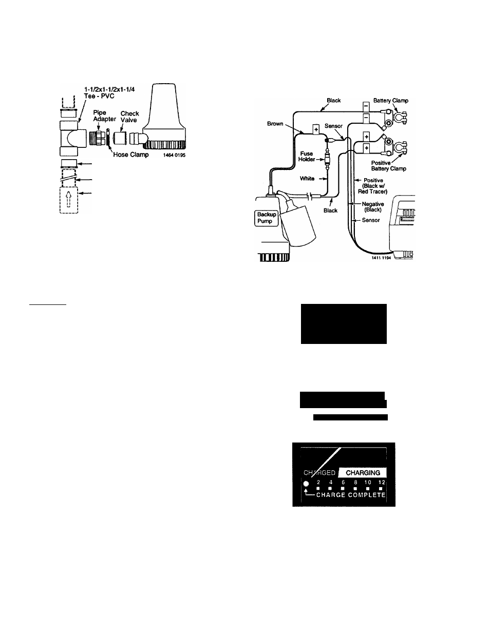
11. Put clamp on adapter, leave loose. Motmt check valve in
adapter; thread assembly into tee.
12. Slip pump into check valve. Tighten clamp.
Reducer Bushing (2 Supplied)
Main Pump Discharge Pipe
Check Valve to Prevent
Recirculation into Sump
Figure 2B — Installation Diagram
13. Make sure battery is fully charged; then check operation
by disconnecting power to primary sump pump and fill
ing sump until Backup Sump Pump starts. Run Backup
Pump through one complete cycle.
ELECTRICAL CONNECTIONS
A
warding
Hazardous voltage. Can cause serious or
fatal electrical shock. Review safety instructions, Page 2, be
fore operating charger.
If your outlet is not grounded, install a copper wire (at least
14 gauge) from the outlet box to a cold water pipe. Use
ground clamp on pipe. BE SURE that the cold water pipe
used has metal continuity to electrical ground. Battery
charger is double insulated. DO NOT modify cord or plug.
CHARGER/BATTERY INSTALLATION
NOTICE: Alarm will sound when charger is first connected
to battery. Press ALARM TEST/RESET button on charger. If
alarm continues to sound, discoruiect one charger lead from
-the battery and reconnect it. Press ALARM TEST/RESET
again; alarm will stop sounding.
1. Connect charger as shown in Figure 3.
A. Connect Positive (-H) lead from charger to positive battery
post.
B. Connect Negative (-) lead from charger to negative bat
tery post.
■
C. Third lead from charger is factory connected to lead from
pump motor/float switch.
NOTICE: If charger is connected backwards, pump will
not operate properly, battery will not charge.
2. Plug in power cord to a 115-125 Volt AC outlet delivering
at least 2 amps. Do not use a switch controlled outlet
Mark circaait in main power panel “Backup sump pump
power supply; do not turn ofiT.
3. With charger properly connected and plugged in, the
panel on the front of the charger will appear as in one of
the following:
A. If battery is dead, charger will supply about 10 amps
power (see Figure 4A).
B. If battery is near full charge, charger will deliver about
5 amps power (see Figure 4B).
Figure 3 - Wiring Connections
DC
CHARGED
■'j 2 4 6 8 \o 12
■ ■ ■ ■ ■ ■
^CHARGE COMPLETE
CHARGING
CHARGED I
2
4 le 8
10
12
■CHARGE COMPLETE
B. K
c.
1413 1194
Figure 4 — Battery Backup Control Panel
A. Battery depleted - charging current 10 amps.
B. Battery nearly charged - current about 5 amps.
C. Charge complete - current 0 amps, LED lights up.