Pump installation and operation – Sears 390.306062 User Manual
Page 4
Attention! The text in this document has been recognized automatically. To view the original document, you can use the "Original mode".
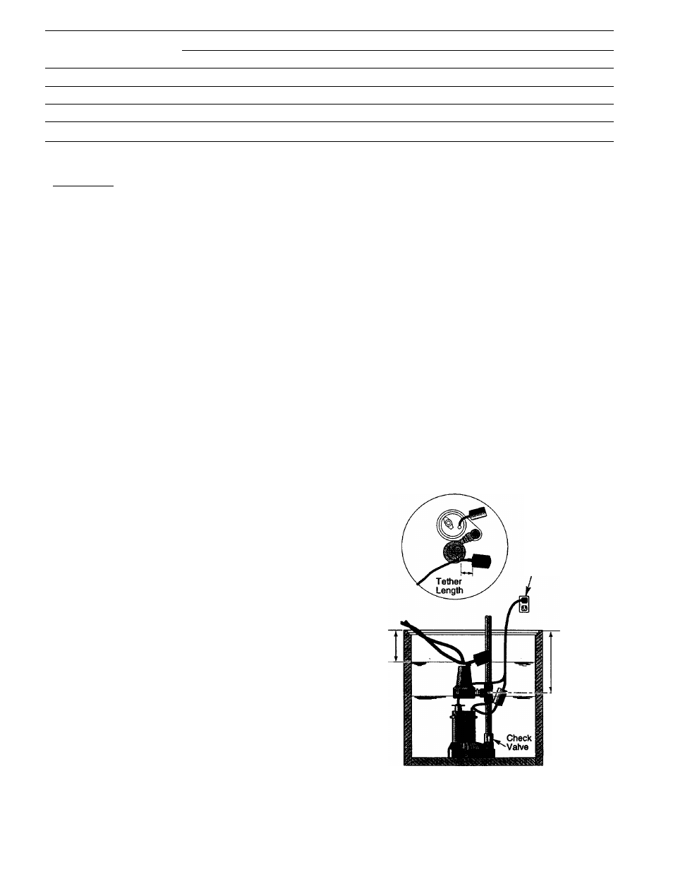
TABLE I Performance Chart/Sears Diehard Size 24M or 27M
VERTICAL PUMPING DISTANCE
8 FEET
10 FEET
12 FEET
Battery Size —
27M
24M
27M
24M
27M
24M
Gallons Per Minute
18.0
18.0
14.5
14.5
11.5
11.5
Hours Available
9.6
8.3
9.9
8.3
6.8
5.7
Total Gallons Pumped
7,212
6,055
5,557
4,939
3,727
3,189
BATTERY REQUIREMENTS
AWARNING Hazardous electrical current. Can cause se
vere bxims and start a fire if battery terminals are short cir
cuited. Install battery in box. To prevent accidental shorting
across battery terminals, strap cover securely on battery box.
Do not leave battery uncovered. Do not allow children to
~play aroimd sump pump installation.
Your Backup Sump Pump depends on the battery used with
it for power. The better the battery, the better the perfor
mance of the pump. We recommend use of a SEARS DieHard
Size 27M or 24M Deep-Cycle Marine battery. This battery
will perform well for many hours and stands up well to long
periods of little or no use.
In an emergency a SEARS DieHard Size 27M or 24M standard
automobile battery may be used. However, an automotive
battery may require charging after only 1 to 2 hours of con
tinuous use, and the repeated charging cycles may cause
early plate failure in the battery.
Use only a new, fully charged battery that will fit in the bat
tery ^x. (maximum size 12-5/8" long, 7" wide and 9-3/8"
high including terminals).
PUMP INSTALLATION
and OPERATION
NOTICE: We recommend a trial fitting of all components
before gluing anything. This wiU allow you to check pump
mounting height, float switch clearance, etc., while adjust
ments can still be easily made.
1 .Mark side of sump six inches down from top.
2. Fill sump until primary sump pump starts; normal high
water level should not be above mark made in step 1. If
it is higher, backup float switch may not swing far enough
for proper operation. To lower high water level, adjust
switch on primary sump pump. Sec primary pump
owner’s manual.
3. Drain sump. Measure down 11 inches from top of sump;
mark this point on side of sump. Install tee with center of
threaded inlet at least this far below top of sump to allow
sufficient room for float switch to swing (see Figure 2A).
4. Make sure that installation will not interfere with primary
sump pump operation as follows:
A. Backup pump installation must not interfere with pri
mary sump pump float switch swing.
B. Normal high water level must never be high enough
to start backup sump piamp.
C. Install a check valve (SEARS Stock No. 2789) in the
main sump pump discharge pipe between the pump
and the backup mounting tee (see Figures 2A and 2B).
Flow through this check valve must be away from the
main sump pump; don’t install it backwards! This
check valve will prevent recirculation into the sump
during battery-powered pump operation.
5. Cut rigid discharge pipe from primary sump pump to
length. Use PVC piping. Tee suppUed is 1-1/2" slip fit; if
necessary use 1-1/4" bushings supplied.
NOTICE: Use any tee that fits sump pump discharge line;
the adapter that is supplied (Key No. 10, Page 7) will fit
any galvanized or plastic 1-1/4" tee. Do not glue the tec
until all parts have been trial fitted.
6. Thread adapter into tec (Figure 2B). When installed,
molded-in ‘up’ should be on top.
7. Install backup pump check valve in adapter. Tab on
backup pump check valve fits into notch at top of
adapter.
8. For trial assembly, slip pump into backup pump check
valve to check pump mounting height and to make sure
that there is no interference with float switch operation
on cither pump; be sure floats will not rub on side of
sump, catch between pump and sump wall, interfere
with each other, etc.
9. Remove pump from adapter; remove tee.
10. Using PVC glue, permanently reinstall tee in primary
sump pump discharge pipe.
Grounded
Electrical
Outlet
6" Min.
(152mm)
11* Min.
(279mm)
13801194
Figure 2A - Standard Installation