Electrical, Wiring connections – Sears 390.252158 User Manual
Page 6
Attention! The text in this document has been recognized automatically. To view the original document, you can use the "Original mode".
ELECTRICAL
A Disconnect power before working on pump, motor, pressure switch, or wiring.
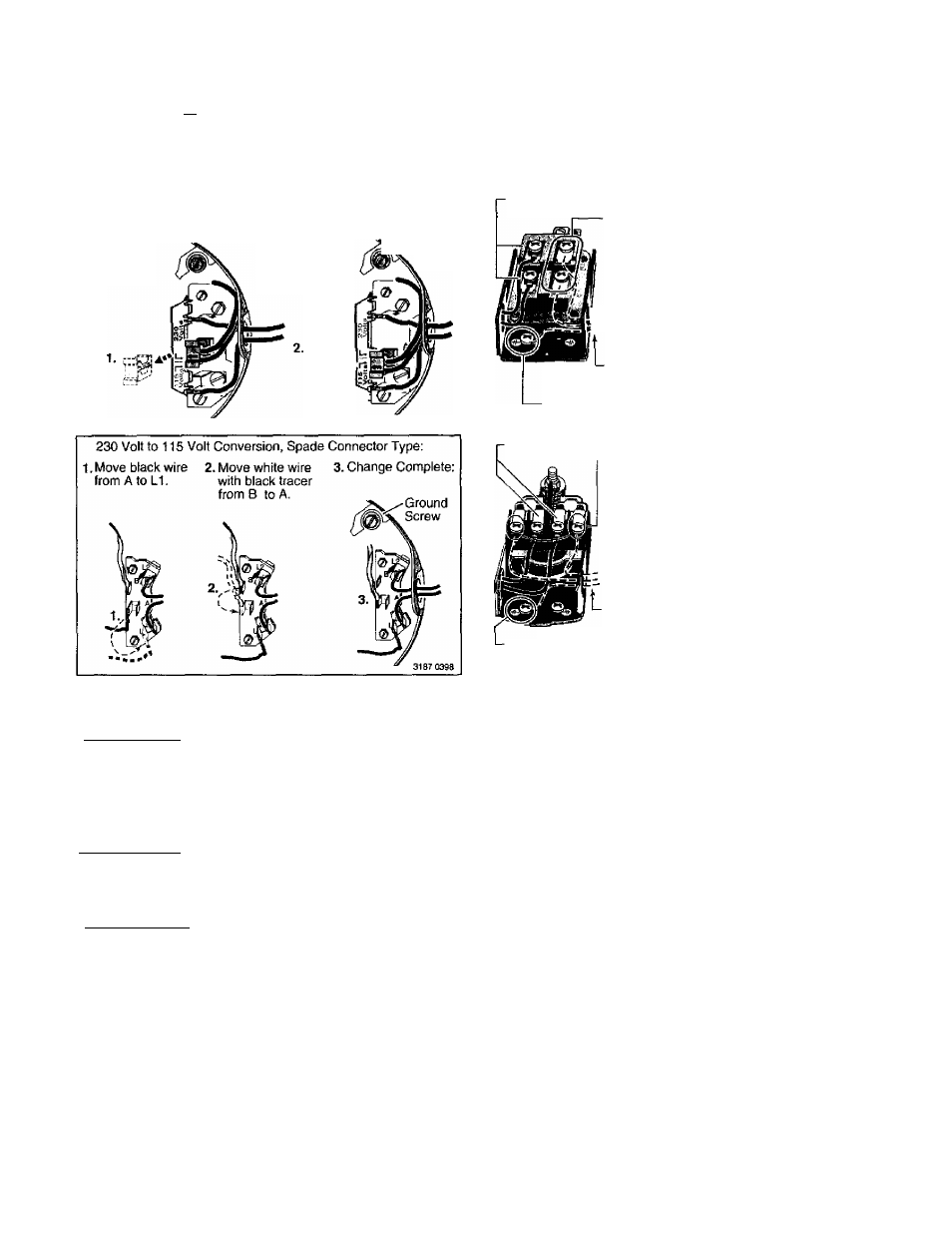
Your Motor Terminal Board (under the motor end cover)
and Pressure Switch look like one of those shown below.
Convert to 115 Volts as shown. Do not change motor wiring
if line voltage is 230 Volts or if you have a single voltage
motor. Connect power supply as shown for your type of
switch and your supply voltage.
230 Volt to 115 Vott Conversion, Plug-ir> Type:
1. Pull plug
straight
out from
terminal
board.
2. Plug in again
with arrow
on plug
pointing to
'115 Volts'.
Ground
Screw
Motor wires connect here.
Power supply wires connect here.
230 Volt: Connect 2 hot wires (black and red)
here and cap the white (neutral) wire. It does
not matter which wire goes to which screw.
115 Volt: Connect one hot wire (black or red)
to one of these screws (it doesn't matter
which one). Connect the white (neutral) wire
to the other screw. Cap any remaining
-- black or red wires.
Clamp the power cable to prevent strain
on the terminal screws.
Connect the green (or bare copper) ground wire
to the green ground screw.
Motor wires connect here.
Power supply wires connect here.
230 Volt: Connect 2 hot wires (black and red)
here and cap the white (neutral) wire. It does
not matter which wire goes to which screw.
115 Volt: Connect one hot wire (black or red)
to one of these screws (it doesn't matter
which one). Connect the white (neutral) wire
to the other screw. Cap any remaining
black or red wires.
Clamp the power cable to prevent strain
on the terminal screws.
■ Connect the green (or bare copper) ground wire
to the green ground screw.
3187 0398
Figure 4; Motor wiring connections through Pressure Switch. Match motor voltage to line voltage.
Connection Procedure;
A WARNING Hazardous voltage. Can shock, bum, or
kill. Connect ground wire before connecting power
supply wires. Use the wire size (including the ground
wire) specified in the wiring chart. If possible, connect
the pump to a separate branch circuit with no other appli
ances on it.
IA WARNING Explosion hazard. Do not ground to a gas
supply line.
WIRING CONNECTIONS
1
.
2
.
A WARNING j pjje hazard. Incorrect voltage can cause a
fire or seriously damage the motor and voids the warranty.
Tlie supply voltage must be within ±10% of the motor name
plate voltage.
-
..
-,
NOTICE: Dual-voltage motors are factory wired for 230
volts. If necessary, reconnect the motor for 115 volts, as
shown. Do not alter the wiring in single voltage motors.
Install, ground, wire, and maintain your pump in compli
ance with the National Electrical Code (NEC) or the
Canadian Electrical Code (CEC), as applicable, and with all
local codes and ordinances that apply. Consult your local
building inspector for code information.
4.
Connect the ground wire first as shown in Figure 4. The
ground wire must be a solid copper wire at least as large
as the power supply wires.
There must be a solid metal connection between the
pressure switch and the motor for motor grounding pro
tection. If the pressure switch is not connected to the
motor, connect the green ground screw in the switch to
the green ground screw under the motor end cover. Use
a solid copper wire at least as large as the power supply
wires.
Connect the ground wire to a grounded lead in a service
panel, to a metal underground water pipe, to a metal
well casing at least ten feet (3M) long, ty tp a ground
electrode provided by the power company or the hydro
authority.
Connect the power supply wires to the pressure switch
as shown in Figure 4.