Assembly of recovery tank and solution tank, Assembly – Sears 175.867029 User Manual
Page 4
Attention! The text in this document has been recognized automatically. To view the original document, you can use the "Original mode".
ASSEMBLY
ASSEMBLY OF RECOVERY TANK
AND SOLUTION TANK
See Figure 2
1. Place Recovery Tank into Solution Tank (align the
word “VACUUM" on Recoveiy Tank with “VACUUM”
on Solution Tank) and secure with Metal Latch.
2. Insert the plug on the Short Cord from the Sol ution Tank
into the Recovery Tank Power Head.
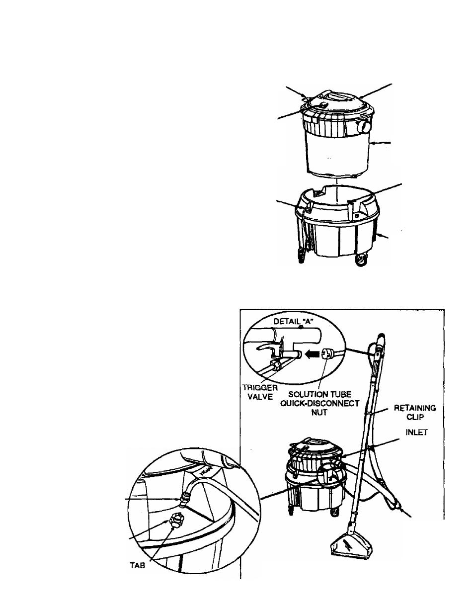
ASSEMBLY OF HOSE, WANDS,
NOZZLE AND SOLUTION TUBING
See Figure 1
1. Assemble the two Straight Wands.
2. Assemble the upper Straig ht Wand to the Angled Wand
of the Hose.
3. Assemble the Floor Nozzle to the lower Straight Wand.
NOTE: Be sure locking button engages properly when
assembling straight wands, angled wand, and floor
nozzle.
4.
Push thè Solution Tube Quick-Disconnect Nut onto
Trigger Valve. Twist clockwise to lock. See DETAIL "A"
- Fig. 3.
5.
Snap Solution Tubing into Retaining Clips on the
Angled Wand and Straight Wands. Connect other end
of Tubing to Carpet Tool.
6.
Attach the Vacuum Hose to Recovery Tank inlet
(Vacuum Inlet).
7. Insert the Plastic Insert of the Soiutton Tubing into the
Coupling of the Solution Tank. See DETAIL *B"~Fig. 3.
NOTE: To remove the Plastic Insert depress the Tab
and gentfy pull on the Plastic Insert. Be careful to pull
on the Plastic I nsert and not the Tubing as damage may
occur.
PLASTIC INSERT
COUPLING
POWER
CORD
PLUG
SHORT
CORD IN
HERE
SHORT
CORD
POWER
HEAD
.RECOVERY
TANK
METAL
LATCH
SOLUTION
TANK
Hg.2
VACUUM
HOSE
DETAIL “B"
Rg-3