Warning, Installing regulator, Installation and break-in procedures – Sears Craftsman 919.154320 User Manual
Page 7: Location of the air compressor, Lubrication and oil, Extension cords, Installation and breakhn procedures, Location of air compressor, Assembly instructions
Attention! The text in this document has been recognized automatically. To view the original document, you can use the "Original mode".
ASSEMBLY INSTRUCTIONS
Tools Needed for Assembly
• pipe thread sealant (not included)
• an adjustable wrench for attaching the pressure
regulator
® a 9/i6" socket or open end wrench for attaching the
wheels and hose adapter.
• a open end wrench for attaching the air pressure
gauges
• a 3/i6" hex key for installing the plug in the regulator
• a %" open end wrench to tighten handle screws
^ a #2 Phillips screwdriver for attaching the control
cover.
Installing Wheels, Handle, Rybber Foot Strip
WARNING
1. Dip the handle grip in soapy water and slide into posi
tion as shown on photo on page 6 or page 12.
2. Attach the handle to the inside of the compressor sad
dle by pushing the handle in, until the slot in the handle
engages with the tabs in the saddle. Pull the handle
back and install the two screws, one on each side of
the saddle. Tighten securely.
It may be necessary to brace or support one
end of the outfit when attaching the wheels
and the rubber foot strip, because the air
compressor will have a tendency to tip.
3. Remove the protective paper strip from the adhesive
backed rubber foot strip. Attach the rubberfoot strip to
the bottom of the air tank leg. Press firmly into place.
4. Attach one wheel to each side of the air compressor.
Use one shoulder bolt and one nut for each wheel.
Tighten securely.
Installing Regulator
Use a small amount of pipe thread sealant on all pipe
thread joints.
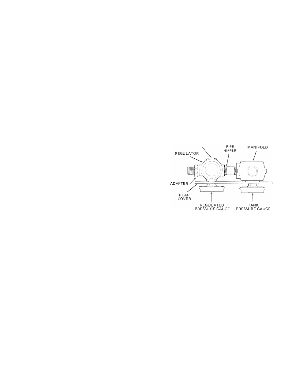
Install the regulator on the end of the manifold using the
short pipe nipple. The arrow on the bottom of the
regulator must point away from the manifold in order for
the regulator to function properly.
Install the adapter and plug in the regulator. The plug is
supplied with the regulator. Install the rear cover and the
gauges at the same time. See diagram below.
Install the control cover. Fasten it to the manifold using
the Phillips screw. Install the plastic mounting ring to the
regulator to fasten the top of the control cover. See photo
on page 6.
INSTALLATION AND BREAK-IN PROCEDURES
Location of the Air Compressor
Locate the air compressor in a clean, dry and well venti
lated area. The air filter must be kept clear of obstruc
tions which could reduce air delivery of the air
compressor. The air compressor should be located at
least 12" away from the wall or other obstructions that
will interfere with the flow of air. The air compressor head
and shroud are designed to allow for proper cooling. If
humidity is high a Sears air filter can be installed to
remove excessive moisture. Follow the instructions
packaged with the air filter tor proper installation.
Lubrication and Oil
This unit needs no additional lubrication or oiling.
Extension Cords
Use extra air hose instead of an extension cord to avoid
voltage drop and power toss to the motor.
If an extension cord must be used, be sure it is;
• a 3-wire extension cord that has a 3-blade grounding
plug, and a 3-slot receptacle that will accept the plug on
the product.
• in good condition.
• no longer than 50 feet.
• 12 gauge (AWG) or larger. (Wire size increases as
gauge number decreases. 10 AWG and 8 AWG may
also be used. DO NOT USE 14 or 16 AWG.)