Operation – Sears 390.2508 User Manual
Page 9
Attention! The text in this document has been recognized automatically. To view the original document, you can use the "Original mode".
OPERATION
Screw impeller on shaft (clockwise) while holding
shaft with 7/1
6
" open end wrench on shaft flats. This
will automatically locate seal in place. See Figure 11.
FACE OF
SEALING WASHER
IMPELLER
IMPELLER HUB
SHAFT
SHOULDER
RUBBER DRIVE RING
Figure 11
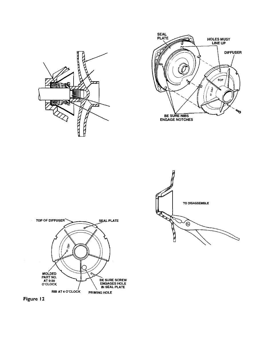
Remount diffuser on seal plate. Be sure diffuser is
right side up as follows (see Figures 13 and 14).
a. Rib next to priming hole should be at six o'clock
position;
b. Part number (N1-28P) should be between nine
o’clock and ten o’clock.
Both mounting screws must engage screw holes
in seal plate. Sec Figure 12.
Be sure rubber pad (Figure 12; Key No. 8, Page
12) stays in place on top of diffuser.
c.
BE SURE RUBBER PAD
STAYS IN PLACE ON
BE SURE SCREW
Figure 13
Installing Copper Insert
NOTE: If the copper insert (Key No.
4
. ,
Page 12) moves
or shifts during seal removal, it should be removed and
reinstalled.
1. Remove copper insert as shown in Figure 14. do not
deform.
Figure 14
2. Replace copper insert:
A. Clean off surplus Permatex* from around insert cav
ity. Be carehil not to scratch or mark the machined
bore. It is important that this area be clean no no old
Permatex lodges behind the new insert and causes im
proper seating.
* “permatex” is a registered trademark of Permatex Co. Irtc.