Sears 919.17632 User Manual
Page 6
Attention! The text in this document has been recognized automatically. To view the original document, you can use the "Original mode".
THIS MANUAL IS DESIGNED
TO MAKE IT AS EASY AS POSSIBLE
FOR YOU TO SET UP, OPERATE AND MAINTAIN
YOUR NEW CRAFTSMAN AIR COMPRESSOR
GENERAL INFORMATION
You have purchased an air compressor outfit consisting
of a 2 cylindersingle stage ar compressor pump with air
tank, an air hose assembly, wheels, a foot extension
bracket and handle. You will also find an air chuck and a
helpful “Power Painting With Sprayers" booklet. This air
compressor
can
be
either
ponable
or
permanendy
mounted in one place.
These units can be used for operating caulking guns,
grease guns, airbrushes, sandblasters, air tools, etc., or
inflating tires and plastic toys, spraying weed killer, in
secticides. etc.
GENERAL DESCRIPTION OF OPERATION
To compress air, the pistons move up and down in the
; cylinder. On the downstroke, air is drawn in through the
I
air intake valve. The exhaust valve remains closed. On
the upstroke of the piston, air is compressed. The intake
valves close and compressed air is forced out through
I the exhaust valve, through the check valve and into the
j airtfflik. Working air is not available until the compressor
I
has raised the air tank pressure above that regulred at
■ the air outlet. Since the air tank pressure Is usually
i greater than what is needed, the tank air Is fed to the air
I
outlet through a regulator. The air intake opening at the
end of the console must be kept dear of obstructions
which could reduce air delivery of the compressor.
ASSEMBLY INSTRUCTIONS
Tools Needed For Assembly
Tools needed are: (1) a ®/is" s»d
for attaching the wheels: and (2) a ^/le" socket or open
end wrench for attaching the foot extension bracket.
Attaching Wheels, Handle, Etc.
V/ARNING
THE
AND HANDLE DC i40T
PROVID“
adequate
CLEARANCE,
STA
BILITY
OR
SUPPORT
FOR
PULLING
THE
UNIT UP OR DOWN STAIRS AND STEPS.
THE UNIT MUST BE LIFTED OR PUSHED UP
A RAMP,
See diagram on page 10 for attaching wheels (40 or
40A), foot extension bracket (45) and handle (48). The
nuts and bolts can be found in a plastic bag which is
enclosed with tte Owner's manuals, air hose. etc. Refer
to the illustration. Page 10. Key No’s. 28, 41,42, 44, 46
and 4Z
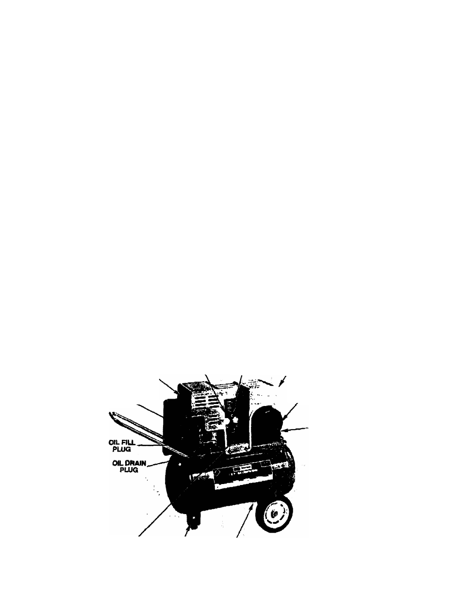
AIR
INTAKE
FILTER
AIR COMPRESSOR
PUMP
ON-AUTO/OFF
SWITCH
S«sETY
VALVE
CONSOLE
RESET BUTTON
MOTOR
AIR OUTLET POOTBCTENSION DRAIN
CONNECTION BRACKET COCK
w
EL
v
E
Figure 1