Sears 645B User Manual
Page 5
Attention! The text in this document has been recognized automatically. To view the original document, you can use the "Original mode".
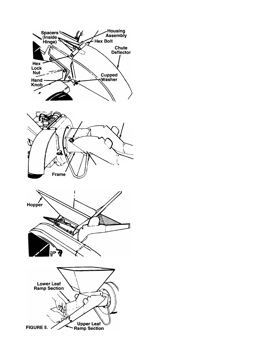
FIGURE 2.
Stop
Washer
Lower
Leaf Ramp
Section
FIGURE 3.
Hex Bolt
8-3/8" Long
Flat Washer
Hex Lock Nut
Self-Tapping
Screws
FiGURE 4.
A
WARNING:
Make
certain
the
spark
plug
wire
is
disconnected
and
moved
away
from
the
spark
piug
before
assembling
the shredder.
AHACHING THE CHUTE DEFLECTOR
(See Figure
2
)
1.---Remove the hand knobs and cupped washers
-------- from each side of the discharge opening on the
left side of the shredder.
2.
Remove the hex lock nut, two spacers and hex
bolt from inside the hinge on the housing assem
bly. Do not remove one spacer from the hex bolt.
3.
Place the chute deflector in position on the dis
charge
opening.
Insert
hex
bolt
and
spacer
through
hinge
on
chute
deflector
and
housing
(spacer fits inside of hinge). See figure 2.
4.
Place the second spacer over the hex bolt, inside
the other part of the hinge. Secure with hex lock
nut. Tighten securely.
5.
Secure both sides of the chute deflector to the
housing
using
the
hand
knobs
and
cupped
washers
(cupped
side
of
washers
go
against
the
chute deflector).
A
WARNING:
Do
not
operate
this
chipper-
shredder
unless
the
chute
deflector
has
been
properly
installed
and
is
secured
with the hand knobs.
-ATTACHING THE LOWER LEAF RAMP SECTION
(Hardware A)
Insert
hex
bolt
8-3/8"
long
through
lower
leaf
ramp
section and frame. Secure with flat washers 5/16" I.D.
and hex lock nut. Make certain the edges of the lower
leaf
ramp
section
are
underneath
the
stop
washers.
See
figure
3.
Plastic
insert
in
hex
nut
should
face
away
from
lower
leaf
ramp
section.
Tighten
hex
nut
until parts are snug, but so lower leaf ramp section
can still be rotated on the frame.
AnACHING THE HOPPER
When attaching the hopper, first remove the five self
tapping screws from the frame of the unit. Place the
■ hopper in position on the shredder. See figure 4. Start
all five self-tapping screws, then tighten securely using
a 1/2" socket wrench.
ATTACHING THE UPPER LEAF RAMP SECTION
(Hardware B)
Place the edge of upper leaf ramp section inside the
lower
leaf
ramps
section.
Secure
with
four
truss
machine screws and hex lock nuts. The heads of the
truss machine screws should be to the inside of the
upper
leaf
ramp
section.
Start
all
screws
and
nuts,
• then tighten securely. See figure 5.