Assemi3ly instructions – Sears 645B User Manual
Page 4
Attention! The text in this document has been recognized automatically. To view the original document, you can use the "Original mode".
ASSEMI3LY INSTRUCTIONS
a
ATTACHING THE LOVUER A
■J LEAF RAMP SECTION
Hex Bolt
-5/16-18
X
8-3/8" Long
Flat ^--------------------- -
Washer
—\
5/16" I.D.
i f
J 1
Hex Lock
Nut 5/16-18
Thread
IMPORTANT:
This
unit
is
shipped
WITHOUT
GASOLINE
or
OIL.
After
assembly,
see
separate
engine
manuai
for
proper
fuel
and
engine
oil
rec
ommendations.
NOTE: To determine right and left hand sides of your
shredder,
stand
behind
the
unit
with
the
engine
the
farthest away from you. See figure 7.
Your
shredder
has
been
completely
assembled
at
the
factory,
except
for
the
hopper,
lower
and
upper
leaf
ramp
sections,
chute
deflector
and
the
catcher
bag.
The
hardware
pack
and
safety
glasses
are
also
included in the carton.
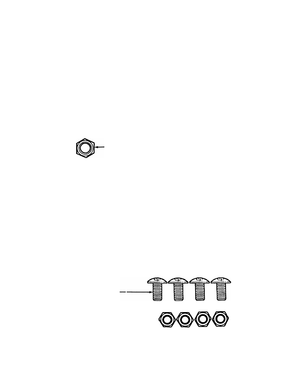
The hardware pack contains the parts shown in figure
1
(shown full size).
TO REMOVE SHREDDER FROM CARTON
1.
Remove staples, break glue on top flaps, or cut
tape
at
carton
end
and
peel
along
top
flap
to
open carton.
2.
Remove
loose
parts
if
included
with
unit
(i.e.,
owner’s manual, etc.).
3. Cut along dotted lines and lay carton down flat.
4. Remove packing material.
5.
Roll
or
slide unit out of carton. Check carton
thoroughly for loose parts.
TOOLS REQUIRED FOR ASSEMBLY
(1) Phillips Screwdriver
(2)
1/2" Wrenches (one must be a socket wrench)
(2) 7/16" Wrenches or Adjustable Wrenches
B
ATTACHING THE UPPER LEAF RAMP SECTION
Truss Machine
Screws 1/4-20 x 1/2"
Long
Hex Lock Nu :s
1/4-20 Thread-
FIGURE 1.