B. hand filing, C. replace or remove the, Stone and carrier asisembly – Sears 358.356090-3.7/20" User Manual
Page 13
Attention! The text in this document has been recognized automatically. To view the original document, you can use the "Original mode".
B. HAND FILING
Sharpen the side plates by hand after every 3rd
to 5th time the Power Sharp® System is used.
Items Required:
Gloves
flat file
5/32” file
vise
file holder
NOTE: If abrasive materials such as rocks, nails,
sand or dirt are contacted fay the chain, the side
plates should be checked more often. Damage
to the cutters caused by abrasive materials
usually results in discoloration spots where the
chrome has been worn away. Cutter side plates
should be filed until these spots are removed.
1. Stop the engine.
2. Adjust the chainfor propertension, page 8.
3. Clamp the bar in a vise to hold the chain
steady. Do not clamp the chain.
NOTE: Work at the midpoint of the bar, mov-
ing’the chain forvyard with a screwdriver as
each cutter is filed.
4. Support the square rod on the file holder (with
5/32” round file) on cutter top plate. Figure 21.
5. Hold the file holder level with the 22° guide
mark parallel to guide bar. Figure 22.
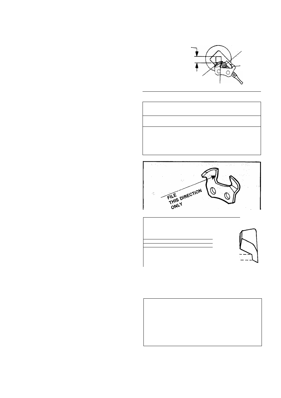
6. File from inside toward outside of cutter in
one direction only — 2 or 3 strokes per side
plate edge should be enough. Figure 23.
NOTE: Avoid hitting the top edge of the cut
ters when filing the side plate.
7. Maintain a 1/32” side plate projection. Figure
'
24. ■■
^ ,
■ , -
,
8. File all side plates on one side of the chain,
then move to the other side of bar and file re
maining side plates.
SUPPORT
FLAT SIDE
OF FILE HOLDER
ON TOP OF CUTTER
ROUND FILE
DEPTH
GAUGE
TOP
PLATE
SIDE PLATE
Figure 21
HOLD FILE'.'
HOLDER LEVEL 22°
/ M
WITH THE 22°
GUIDE MARK
parallel
TO
GUIDE BAR /
Figure 22
Figure 23
SIDE
PLATE
\ l
-^1-^1/32”
SIDE PLATE
PROJECTION
1/32”
-------1 MAXIMUM
...
SLmJ-mil
!
TOP ^ U- 22°
PLATE/ I
TOP VIEW
OF CUTTER
- - f ' “
Figure 24
C. REPLACE OR REMOVE THE
STONE AND CARRIER ASiSEMBLY
1. Remove Carburetor Cover and Bar Clamp.
2. Remove the two screws which hold cartridge
assembly to crankcase. Figure 25.
3. Discard old assembly.
4. Install new cartridge assembly.
NOTE: Be careful not to let the Siide Button
fall out.
5. Reinstall Carfauretof Cover and Bar Clamp.
STONE
CARTRIDGE'^
ASSEMBLY
Figure 25
13