Carrier 58GSC User Manual
Page 2
Attention! The text in this document has been recognized automatically. To view the original document, you can use the "Original mode".
8. Install new natural gas pilot orifice (silver, 1/2-in. long,
0.018-in. orifice diameter).
9. Reinstall pilot gas supply tube bn pilot. When tighten
ing pilot tube, use backup wrench and turn pilot so
that it will be on the same angle as before.
Do not
rein
stall pilot at this time.
B. Installation of Main Burner Orifices
1. Remove secondary air shield.
2. Remove main burners from manifold.
3. Remove and discard No. 55 (or field-installed per local
application) orifices from manifold.
4. Install No. 45 main burner orifices provided in kit.
Finger-tighten orifices at least one fxill turn so as not to
cross-thread, then tighten with wrench. There are
enough orifices in each kit for the largest furnace. Dis
card extra orifices.
The full input rating with No. 45 main burner natural gas
orifices is approved for altitudes up to 2000 ft. The input
rating for altitudes above 2000 ft must be reduced by 4%
for each 1000 ft above sea level. Consult the current edition
of the National Fuel Gas Code NFPA No. 54/ANSI Z223.1,
Part 8.1 and Appendix F Table F-4, for input adjustment
for high altitude.
5. Install new burners with N0^ reduction screens on
manifold. See Figs. 2 and 3 for proper orientation of
burners and pilot.
6. Reinstall pilot assembly.
7. Reconnect pilot supply tube to gas valve.
8. Reconnect electrode wire to spark generator.
9. Reinstall secondary air shield.
C. Conversion of Gas Valve and Inlet Gas Pressure
Check
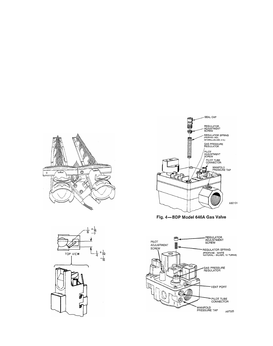
1. Remove regulator seal cap. See Fig. 4 for BDP 646A or
Fig. 5 for White-Rodgers 36E Gas Valve.
2. Remove adjustment screw and propane gas regulator
spring (red for 646A and white for 36E).
3. Install proper natural gas regulator spring (silver) pro
vided in kit, in proper gas valve. See Table 1.
4. Replace regulator adjustment screw.
Do not
reinstall
regulator seal cap at this time.
5. Remove 1/8-in. pipe plug from inlet pressure tap on gas
valve.
REGULATOR
A88463
Fig. 2—Pilot/Burner Relationship
-REGULATOR
SEAL CAP
Fig. 3—Position of Pilot Electrode to Pilot
Fig. 5—White-Rodgers Model 36E Gas Valve