Carrier 58VCA User Manual
Page 7
Attention! The text in this document has been recognized automatically. To view the original document, you can use the "Original mode".
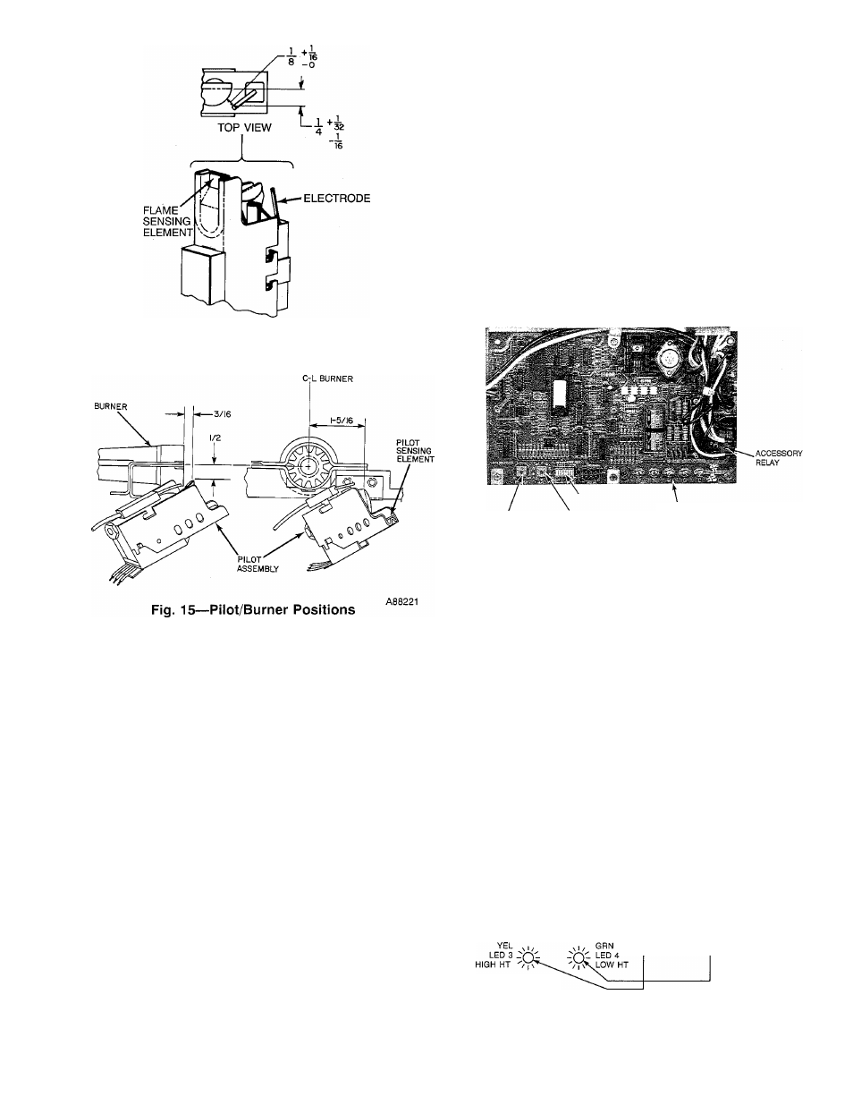
A79080
Fig. 14—Position of Electrode to Pilot
With power disconnected to the unit, check all electrical connec
tions for tightness. Tighten all screws on electrical connections. If
any smokey or burned connections are found, disassemble the
connection, clean all parts, strip wire, and reassemble properly and
securely.
Reconnect electrical power to the unit and observe unit through 1
complete operating cycle. Electrical controls are difficult to check
without proper instrumentation.
ELECTRICAL NOISE AND INTERFERENCE - This equip
ment generates and uses radio frequency energy and, if not
installed and used properly (in strict accordance with the manu
facturer’s instructions), may cause interference with radio and
television reception. The unit has been tested and found to comply
with the limits for a Class B computing device in accordance with
the specifications in Subpart J of Part 15 of Federal Communica
tions Commission (FCC) Rules, which are designed to provide
reasonable protection against such interference in a residential
installation. However, there is no guarantee that interference will
not occur in an installation. If this equipment does cause interfer
ence to radio or television reception (which may be determined by
turning the equipment off and on), the user is encouraged to try
correcting the interference by 1 or more of the following measures:
(1.) Reorient receiving antenna.
(2.) Relocate receiver with respect to equipment.
(3.) Move receiver away from equipment.
(4.) Plug receiver into different outlet so that equipment
and receiver are on different branch circuits.
(5.) Slide Ferrite core electrical noise suppressor over
thermostat wire.
If necessary, the user should consult the dealer or an experienced
radio/television technician for additional suggestions. The follow
ing booklet prepared by the FCC may be helpful:
“How to Identify
and Resolve Radio-TV Interference Problems.”
This booklet is
available from the U.S. Government Printing Office, Washington,
DC 20402, Stock No. 004-000-00345-4.
SERVICE DIAGNOSTICS — This furnace has a light emitting
diode (LED) display to aid the installer, homeowner, or service
technician in installing or servicing the unit. (See Fig. 17.) The
display can be seen through the view port provided in the blower
door. To decipher the meaning of the display, refer to Fig. 17 or the
fault code label inside the control access door.
SETUP SWITCHES
BLOWER OFF DELAY COOLING AIRFLOW
ADJUSTMENT
ADJUSTMENT
24V TERMINALS
A92099
Fig. 16—Microprocessor Control Center
View the display through the port provided in the blower door. If
YEL LED 3 is lit continuously, the furnace is operating in the
high-heat mode. If GRN LED 4 is lit continuously, the furnace is
operating in the low-heat mode. If the lower RED LED 1 is lit
continuously, the furnace is operating in the emergency-heat
mode. If the upper RED LED 2 is lit continuously, the micropro
cessor has malfunctioned.
DO NOT REMOVE THE BLOWER DOOR IF LED’s ARE
FLASHING; the fault code will be lost.
Alternate flashing of the YEL and GRN LED’s indicates that a
fault has occurred during operation. Count the number of times the
YEL LED flashes and then count the number of times the GRN
LED flashes. Once the fault code has been determined, refer to
Table 1 or the fault code label inside the control access door to
decipher the meaning of the display.
RED LED 2
MALFUNCTION
O
COUNT THE
NO. OF ^
FLASHES '
I
(4)
o
RED LED 1
EMER HT
COUNT THE
NO. OF
FLASHES
I
■ = 42 FAULT
INDUCER OUTSIDE
VALID SPEED
RANGE
Fig. 17—Fault Code LED’s
A87348