A warning – Carrier 58VCA User Manual
Page 6
Attention! The text in this document has been recognized automatically. To view the original document, you can use the "Original mode".
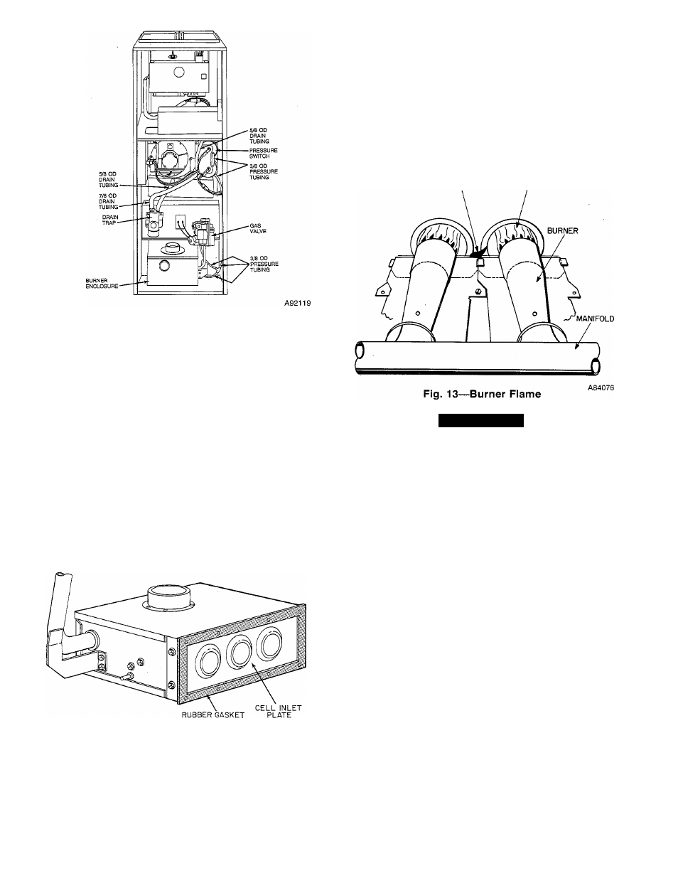
Fig. 11—Downflow Furnace Pressure and Drain
Tubing Diagram
(2.) Connect drain tube from collector box to inducer
outlet box.
b. Downflow furnace only:
(1.) Reconnect vent pipe. Be sure clamps are tight.
(2.) Reinstall vent pipe enclosure.
(3.) Connect drain tube from collector box to inducer
outlet elbow.
6. Upflow furnace only—reinstall main control box.
a. Reinstall main control box on blower shelf.
b. Reconnect 15-circuit connector at main control box on
blower shelf.
7. Check condition of gasket on cell inlet panel of burner
enclosure. Replace gasket if necessary. (See Fig. 12.)
Fig. 12—Burner Enclosure
8. Install gas control assembly in furnace.
9. Install diffuser and burner enclosure front.
10. Reconnect pilot leads at 3-circuit connector.
11. Reconnect high-voltage lead to spark generator.
12. Reconnect gas valve leads at 6-circuit connector.
A87301
13. Reconnect pressure tubes to gas valve and burner enclosure.
Be sure tubes are not kinked.
14. Using a backup wrench, install gas pipe in gas valve.
15. Reconnect gas pipe at ground joint union.
16. Reconnect combustion-air pipe. Tighten hose clamps.
17. Replace blower door only.
18. Turn ON gas and electrical supplies.
19. Check furnace operation through 2 complete operating cycles.
Lxjok through sight-glass in burner enclosure to check burners.
Burner flames should be clear blue, almost transparent. (See
Fig. 13.)
p||_Q.^
flame
burner
flame
A WARNING
Never use matches, candles, flame, or other sources of
ignition to check for gas leakage. Use a soap-and-water
solution. Failure to follow this warning could result in a fire,
personal injury, or death.
20. Check for gas leaks.
21. After condensate starts to drain, check for condensate leaks.
22. Replace control door.
Step 5—Clean Condensate Drainage System
1. Disconnect 5/8-in. drain tube from bottom of inducer housing.
(See Fig. 10 or 11.)
2. Disconnect 7/8-in. drain tube from collector box. (See Fig. 10
or 11.)
3. Disconnect condensate drain line from drain trap at compres
sion fitting.
4. Remove 1/4-in. screw(s) securing strap on drain trap.
5. Remove drain trap/hose assembly from furnace and flush with
water until clean.
6. Flush external condensate drain line with water until clean.
7. Reassemble condensate drainage system by reversing items 1.
through 5.
Step 6—Pilot Assembly
Check the pilot assembly and clean if necessary at the beginning of
each heating season. The pilot flame should be high enough for
proper impingement of the safety element and to light the burners.
Remove any accumulation of soot and carbon from the safety
element. Check spark electrode gap. (See Fig. 14 for proper spark
gap and Fig. 15 for correct pilot location.)
Step 7—Electrical Controls and Wiring
NOTE:
There may be more than 1 electrical supply to the unit.