Fig. 7—cleaning primary heat exchanger cell – Carrier 58VCA User Manual
Page 5
Attention! The text in this document has been recognized automatically. To view the original document, you can use the "Original mode".
A88489
Fig. 7—Cleaning Primary Heat Exchanger Cell
(5.) Repeat procedures (previous) until each furnace cell has
been cleaned.
(6.) Using vacuum cleaner, remove residue from each cell.
(7.) Using vacuum cleaner with soft brush attachment,
clean burner assembly.
Step 4—Reassemble Furnace (After Cleaning Heat Ex
changers)
1. Reinstall coupling box(es):
c. Apply sealant releasing agent (Pam) to coupling box flange
and cell panel where coupling box flange matches. (See
Fig. 8.)
APPLY RELEASE AGENT TO AREA
INDICATED BY SHADING
COUPLING BOX
(INSIDE VIEW)
Fig. 8—Inside View of Coupling Box
A87318
d. Apply a generous bead (3/16-in. diameter) of G.E. RTV
122, 162, or Dow-Corning RTV 738 sealant (NO substi
tute is permissible) to flange of coupling box. (See Fig. 8.)
Your distributor/dealer should have G.E. RTV 122, 162, or
Dow-Corning RTV 738 sealants in stock.
e. Being careful not to smear sealant, position coupling box so
that slot in insulation is on left side and install coupling
box.
2. Reinstall inducer assembly.
a. Upflow furnace only —Be sure small round gasket(s) is in
place between blower shelf and inducer housing.
b. Apply sealant releasing agent (Pam) to collector box.
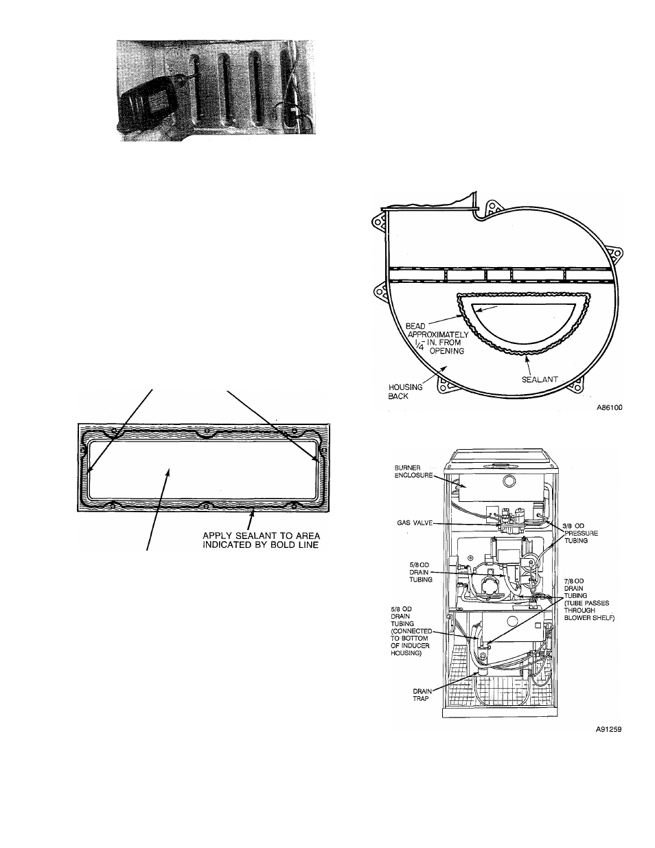
c. Apply 1/8-in. diameter bead of G.E. RTV 122, 162, or
Dow-Corning RTV 738 sealant to back of inducer housing.
Apply sealant around inlet air opening. (The sealant should
be about 1/4 in. from the edge of the inlet air opening.) (See
Fig. 9.)
d. Install inducer assembly on collector box and support
bracket to coupling box.
e. Connect 6-circuit inducer motor connector to inducer
controller. Reconnect 6-circuit connector from pressure
switches to main harness. (See Fig. 18.)
f. Reconnect pressure tubes to pressure switch. (See Fig. 10 or
11
.)
3. Connect small drain tube from top of trap to fitting on bottom
of inducer housing. (See Fig. 10 or 11.)
4. Connect 7/8-in. drain tube to trap and collector box; tighten
hose clamps. (See Fig. 10 or 11.)
Fig. 9—Back of Inducer Assembly Housing
Fig. 10—Upflow Furnace Pressure and Drain
Tubing Diagram
5. Reinstall vent pipe and drain tube,
a. Upflow furnace only;
(1.) Reconnect vent pipe. Be sure clamps are tight.