Sequence of furnace operation – Carrier 58SSB User Manual
Page 5
Attention! The text in this document has been recognized automatically. To view the original document, you can use the "Original mode".
GND,
rh
WHT cnsv)
YEL C208.230)
WHT Cl 15V) BLUC208V) RED C230V)
,
PR1-2
L2
PIN 6 FOR 115 VAC
PIN 9 FOR 208,230 VAC
BCR
Dl-4
GND
ILK
MTRl
ONR
PCBl
PCB2
PLl
PL2
PL3
PL4
PL5
RES
TB3
TB4
TRAN
^ >-
0
Hi
BLOWER CTRL RELAY DPST
DIODE BRIDGE
GROUND
SWITCH, BLOWER DOOR INTERLOCK
SPST-N.O. CGA5 FURNACE ONLY)
MOTOR CECM) BLOWER
ON/OFF RELAY DPST
P.C. BOARD CECM BLOWER CTRL)
P.C. BOARD CINTERFACE)
CONNECTOR CECM BLOWER CTRL)
CONNECTOR CECM BLOWER MTR)
CONNECTOR CFURN./HEATPACK CTRL.)
CONNECTOR (OUTDOOR SECTION)
CONNECTOR (EXPANSION VALVE)
RESISTOR CADJ: TEMP. RISE)
TERMINAL BLOCK (FURNACE CTRL)
TERMINAL BLOCK (THERMOSTAT)
TRANSFORMER, 120, 208-230VAC
PRI/24VAC SEC
LE6END
FIELD SPLICE
PLUG RECEPTACLE
JUNCTION
TERMINAL PCB FACTORY CONN.
TERMINAL FIELD CONN.
FACTORY WIRING C120V AC)
FACTORY WIRING CLOW VOLTAGE)
FIELD WIRING
CONDUCTOR ON PCB2 (INTERFACE)
SCREW TERMINAL FOR FIELD CONN.
D.C. GROUND
EQUIP. GROUND
5.
NOTES:
T2 INTERNALLY CONNECTED TO EQUIP
MENT GROUND.
REPLACED DAMAGE WIRE WITH AWH
C105"C) WIRE OR ITS EQUIVALENT.
BLOWER MTR CMTRl) HAS THERMAL
OVERLOAD SWITCH.
SYMBOLS ARE ELECTRICAL REPRESENTA
TION ONLY.
SOLID LINES INSIDE PCB2 ARE P.C.
BOARD CONDUCTORS.
303892-301 REV. B
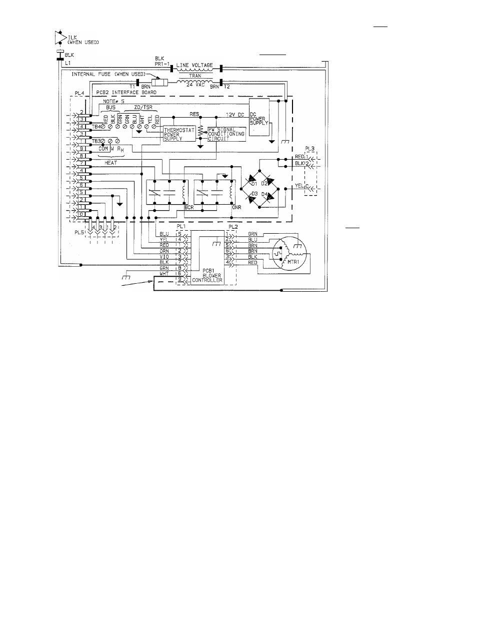
Fig. 7 — ECM Blower Kit Line-to-Line Wiring Diagram
SEQUENCE OF FURNACE OPERATION
Heating Cycle — The control circuit of furnace
shown in schematic wiring diagrams, Fig. 6 and 7, results
in the following sequence of operation for the heating
cycle when used with ECM blower kit:
1. When blower door is in place, 120 volts is supplied
through blower door interlock 9G. Both transformers
lA and TRAN are energized supplying 24 volts to
heating blower relay coil 2E, interface circuit board
PCB2, and outdoor section. When heating blower
relay coil 2E is energized its normally closed contact
is opened.
2. The wall thermostat calls for heat which in turn
transmits necessary signal to CPU in outdoor section
which energizes R and W circuit. This closed circuit
supplies power to 24-volt safety circuit containing
limit switch 7H1, fusible link 11C, manual reset draft-
safeguard switch 7H2, manual reset auxiliary switch
7H3 (when used), and energizes ECM blower motor
MTRl at a low blower speed.
3. Simultaneously, the pick coil of gas'valve 5F, spark
generator 6F, and inducer-motor relay coil 2D are
energized. Inducer-motor relay contacts 2D close
supplying 120 volts to start inducer blower motor 3A.
Also, another set of contacts in inducer-motor relay
2D close in 24-volt circuit, and lock in inducer-motor
relay coil 2D. The coil is locked in until R and W
circuit or safety circuit opens.
4. When pick coil of gas valve 5F is energized, gas flows
to pilot. Pilot gas is ignited by a spark produced by
spark generator 6F. Simultaneously, inducer motor
3A comes up to speed, actuating flow sensing switch
7V, energizing hold coil of gas valve 5F. Pick coil of
gas valve 5F and spark generator 6F are de-energized
when contacts of pilot-flame sensing switch 6H move
from normally closed position, breaking circuit to
pick coil and spark generator. In approximately 50 to
60 seconds, normally open contacts of pilot-flame
sensing switch 6H close, making circuit to MGV (main
gas valve) of gas valve 5F. Gas valve 5F opens in
approximately 10 seconds, allowing gas flow to main
burners, which are ignited by pilot 6H. Simul
taneously, time-delay circuit in furnace control board
is energized. Approximately 60 seconds after gas
valve 5F opens, heating relay coil 2E is de-energized,
which closes 120-volt contacts of heating relay 2E,
energizing blower control relay BCR and on/off relay
ONR on interface circuit board PCB2. This in turn
steps up ECM blower motor MTR 1 to its heating speed.
5. When thermostat is satisfied, the appropriate signal
is transmitted to CPU in outdoor section which de
energizes R and W circuit. This in turn de-energizes
gas valve 5F, inducer motor relay 2D, and solid-state
time-delay circuit on furnace control board. Gas flow
stops immediately to pilot and main burners. After
approximately 105 seconds, heating relay 2E is ener
gized, which opens heating relay contacts 2E supplying
120 volts to interface circuit board PCB2. This causes
blower control relay BCR and on/ off relay ONR to
de-energize allowing ECM blower motor MTRl
to stop.
NOTE: After a brief interruption of either electric or gas
supply, furnace will not resume operation until contacts
of pilot-flame sensing switch 6H move from normally
open to normally closed position.