Furnace location with respect to cooling equipment, Special locations – Carrier 58 Series User Manual
Page 7
Attention! The text in this document has been recognized automatically. To view the original document, you can use the "Original mode".
give rated input at a manifold pressure of 10.5 in. wg.
Check manifold pressure and, if necessary, adjust
pressure.
HIGH ALTITUDE — Ratings are approved for
altitudes to 2000 ft for all gases. Ratings for altitudes
over 2000 ft are 4% less for each 1000 ft above sea
level.
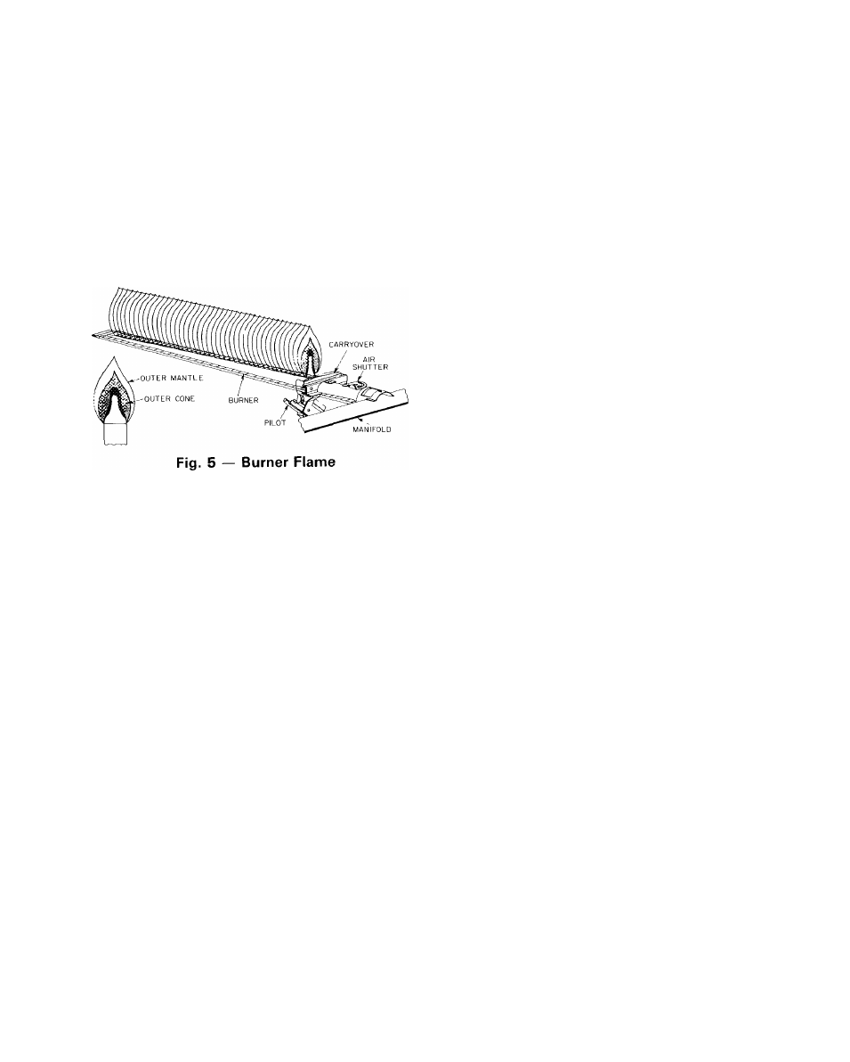
Adjust Main Burner Flame
— The main burner
flame should be clear blue, almost transparent,
with a well-defined inner cone. If there is too much
primary air, the flame will be well defined, but
with a tendency to float or lift off the burner ports.
See Fig. 5.
1. Allow unit to operate 5 minutes.
2. When burners are equipped with primary air
adjustment, adjust each burner by closing air
adjustment device until slight yellow tip appears
on flame; then open, just enough to clear yellow
from flame.
Temperature Rise
— The unit is to be adjusted
within the temperature rise range specified on the
rating plate. Determine the air temperature rise as
follows:
1. Place duct thermometers in return and supply
ducts as near furnace as possible. Be sure ther
mometers do not “see” heat element so that
radiant heat will not affect thermometer read
ings. This is particularly important with straight-
run ducts.
2. When thermometers stabilize, subtract return air
temperature from supply air temperature to
determine air temperature rise.
3. Adjust air temperature rise by adjusting blower
speed. Increase blower speed to reduce tempera
ture rise. Decrease blower speed to raise tempera
ture rise.
Limit Control Safety Check
— This control shuts
off the gas and energizes the blower motor if the
furnace becomes overheated.
The recommended method of checking the limit
control is to gradually block off the return air after
the furnace has been operating for a period of at
least 5 minutes. As soon as the limit has proven
safe, the return air opening should be unblocked to
permit normal air circulation. By using this method
to check the limit control, it can be established that
the limit is functioning properly and will be fail-safe
if there is a motor failure.
FURNACE LOCATION WITH RESPECT
TO COOLING EQUIPMENT
The cooling coil must be installed parallel with
or on the downstream side of the furnace to avoid
condensation in the heating element. When installed
parallel with a furnace, dampers or other means
used to control the flow of air must prevent chilled
air from entering the unit. If the dampers are
manually operated, they must be equipped with
means to prevent operation of either unit unless the
damper is in the full-heat or full-cool position, i
^
SPECIAL LOCATIONS
A gas-fired furnace installed in a residential
garage should be installed so the burners and igni
tion source are located not less than 18 in. above
the floor and the furnace is located or protected to
avoid physical damage by vehicles.
When furnaces are installed in public garages, air
plane hangars, or other buildings having hazardous
atmospheres, the unit should be installed in accord
ance with the recommended good practice require
ments of the National Board of Fire Underwriters.
#