Electrical, Start-up, adjustment, and safety check – Carrier 58 Series User Manual
Page 5
Attention! The text in this document has been recognized automatically. To view the original document, you can use the "Original mode".
k m
6. Insert the smallest flue conneetion pipe at the
highest level consistent with available head-
room or clearance to combustible materials,
when 2 or more vent connectors enter a com
mon gas vent or chimney flue.
7. Extend flue connection pipe thru chimney wall,
flush with inner face of chimney liner and above
extreme bottom to avoid restriction.
WARNING; Never connect into a chimney
serving an open fireplace unless fireplace
opening is sealed off.
8
.
9.
10
.
No portion of the venting system shall extend
into or pass thru any circulating air duct or
plenum.
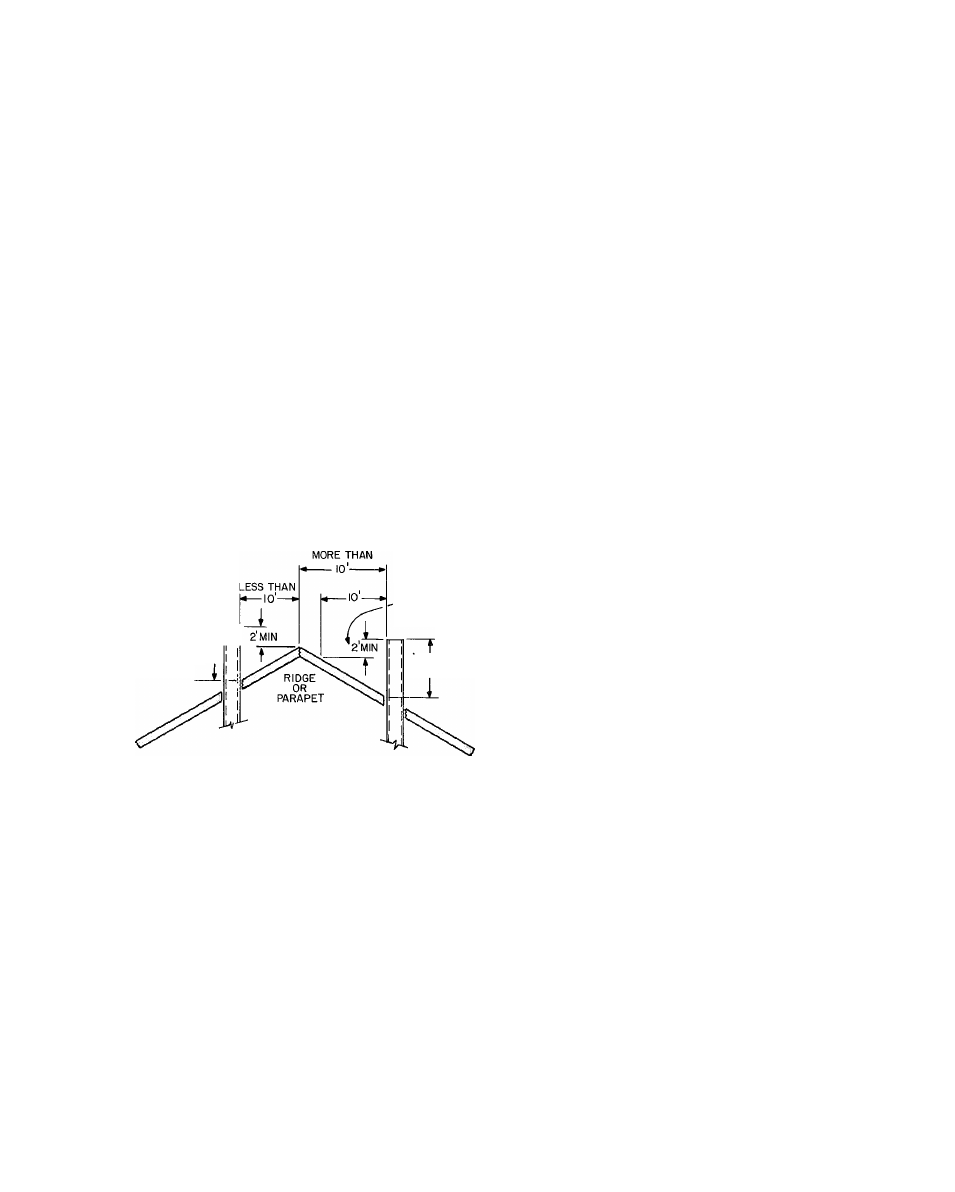
Chimney or gas vent should extend at least 5 ft
above highest connected draft hood and should
extend high enough above roof of any neighbor
ing obstruction so that wind from any direction
will not create positive pressure in vicinity of a
chimney or gas vent outlet. Chimney or gas vent
should extend 3 ft higher than point of emer
gence thru roof, and at least 2 ft higher than any
object within radius of 10 feet. See Fig. 4.
A type-Bl gas vent shall terminate above the
roof surface with a listed cap or roof assembly.
Tn
3 MIN GAS VENT
OR CHIMNEY
HEIGHT ABOVE ANY
ROOF SURFACE
WITHIN 10'
HORIZONTALLY
3MIN GAS VENT
OR CHIMNEY
Fig. 4 — Chimney, Gas Vent Height
ELECTRICAL
IMPORTANT: Before proceeding with the
electrical
connections,
make
certain
that
voltage, frequency, and phase correspond tp
that specified on the furnace rating plate. Also,
check to be sure that the service provided by the
utility is sufficient to handle the additional load
imposed by this equipment. Refer to the unit
rating
plate
for
equipment
electrical
requirements.
" The specific furnace installation instructions con
tain wiring diagrams that show the proper field high-
and low-voltage wiring. Make all connections in
accordance with the National Electrical Code and
any local codes or ordinances that might apply.
^ W.ARNING: The cabinet must have an unin-
terruoted or unbroken ground according to
National
Electrical
Code,
ANSI/NFPA
70-1981, ANSI C1-19SI, or local codes to mini
mize personal injury if an electrical fault should
occur. This may consist of electrical wire or
conduit approved for electrical ground when
installed in accordance with existing electrical
codes. Do not use gas piping as an electrical
ground.
CAUTION; If manual disconnect switch is to be
mounted on the furnace, select a location where
drill or fastener will not contact electrical or
gas components.
NOTE; Use only copper wire between disconnect
switch and furnace. If aluminum wire is used be
tween service panel and disconnect switch, adhere
to the following recommendations.
When making aluminum conductor connections
to copper conductors or terminals, use only con
nectors that are UL approved (marked Al/Cu with
the UL symbol) for the application and wire size.
Do not reduce wire size to fit connector by cutting
off strands. Use properly sized connectors.
After insulation has been stripped from the
aluminum conductor, coat the conductor end with
corrosion inhibitor (Burndy Pentrox A or equiv
alent), and wire-brush the aluminum surface thru
the inhibitor.
CAUTION: Do not wire-brush connectors and
lugs. The plating will be broken.
After cleaning, recoat the aluminum conductor
with inhibitor, and make connection, then coat entire
connection. When it is suspected that the connection
will be exposed to moisture, it is very important to
cover the entire connection completely to prevent
an electrochemical action that will cause the con
nection to fail very quickly.
If aluminum conductors are to be used, the wire
size selected must have a current capacity not less
than that of the copper wire specified, and must not
create a voltage drop between the service panel
and the furnace in excess of 2% of the unit rated
voltage.
Check all electrical connections (both factory and
field) for tightness. This should also be done after
the unit has reached operating temperatures,
especially if aluminum conductors are used.
START-UP, ADJUSTMENT, AND
SAFETY CHECK
Pilot
— Check to be sure that all connections have
been properly made, then proceed as follows;
Light the pilot, using the procedure outlined on
the Lighting Instruction Plate attached to the fur-