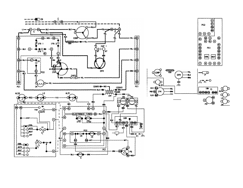
Fig. 14 — typical 3-phase wiring diagram, 1 co o) – Carrier 48NLT User Manual
Page 15
Attention! The text in this document has been recognized automatically. To view the original document, you can use the "Original mode".
FIELD L3
POWER L2
SUPPLY
SIN6LE 5TA6E HEAT S SIN6LE STA6E COOL
TfCRMOSTAT CTYPJ
BLK-
■ RSI -
ORN -
TRAN
BRN
^5—
{j^
I—@
©
ilHl—®
EG
CAPI
1 Co o)
^
CAP2
ICOMPOWB^T
arrangement
“
LEGEND
MV
OFM
p
PC1
PC2
PI
PS
PV
TRANS
ALS1
ALS2
C
CAP. 1,2
CCH
COMP
EG
GV
IPM
IFR1
IFR2
IM
IR
IQN
LS
NOTES:
1. 230-v operation as shown. For 208-v operation, reverse red and orn leads of transformer.
2. Symbols are an electnca) representation only.
3. If any of the original wire, as supplied, must be replaced, use minimum 105'^C wiring
material.
4. Use copper wire only for field power supply leads.
5. Compressor and fan motors provided with inherent thermal protection.
6. Three-phase motors protected under primary single-phase conditions.
Auxiliary Limit Switch (SPST)
NC (Blower)
Auxiliary Limit Switch (SPST)
NC (Rollout)
Contactor
Capacitors (Run)
Crankcase Heater
Compressor
Equipment Ground
Gas Valve
Indoor Fan Motor
Indoor Fan Relay
(SPOT) NO (Cooling)
Indoor Fan Relay
(SPST) NO (Heating)
Inducer Motor
Inducer Relay (DPST) NO
Ignitor
Limit Switch (SPST) NC
©
O
Mam Valve
Outdoor Fan Motor
Pilot (Flame Sensing)
Printed Circuit Board (Blower)
Printed Circuit Board (Inducer)
Pilot Ignitor
Pressure Switch (SPOT) NC
Pilot Valve
Transformer
Field High-Voltage Wiring
Factory High-Voltage Wiring
Factory Low-Voltage Wiring
Field Low-Voltage Wiring
Marked Connection
Unmarked Connection
Internally Connected or
Wirenut
Fig. 14 — Typical 3-Phase Wiring Diagram