Homelite LM-09904-47 User Manual
Page 6
Attention! The text in this document has been recognized automatically. To view the original document, you can use the "Original mode".
2. Install^the front catch using a 3/i-16 x 1” capscrew,
flatwasher and locknut. Tighten the locknut so that it
will hold, securely but still allow the catch to pivot.
(Figure 9).
3.
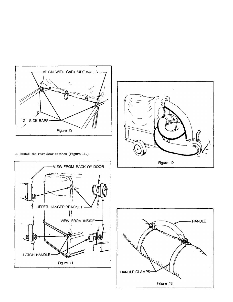
Unfold the canvas and frame assembly so that the front
and rear uprights are in a vertical position. Align the
side "Z" bars with the cart side wall upper edges and
slide the assembly forward onto the cart (Figure 10). Be
sure that the front of the cover frame is toward the front
of the cart. Turn the front catch down over the front
edge of die cart.
4. Secure the four crossbrace tubes with the hardware at
tached (Figure 9).,
7. Place the 6” diameter hose in the cover sleeve and tighten
the strap in the sleeve (Figure 9).
8. Secure one end of the spring to the strap in the cover
sleeve by knotting the end of the strap to the spring. In
sert the other end of the spring through the hole in the
end of the hook. Then place the hook over the lip on the
front of the dump cart body (Figure 9).
Mounting the Roving Nozzle
The roving nozzle attaches to the blower inlet in place of the
hose from the mower. For storage a rack is provided for
installation on the front of the dump cart (Figure 12.)
1. Install the hose flange and a hose clamp on the plain end
of the hose. Secure with one 1/4-20 x 3” machine screw,
lockwasher and hex nut (Figure 4),
2. Install the hose handle clamps the desired distance from
the pickup end of the hose and attach the handle.
(Figure 13),
6. Engage the upper doorframe side capscrews in the upper
hanger brackets and push the bottom edge into place in
the box bed. Engage the rear latches to the lower door
frame side capscrews (Figure 11).