Serial module installation – Winco ASCO 300 Accessory 72A Serial Module User Manual
Page 5
SERIAL MODULE INSTALLATION
(continued)
3
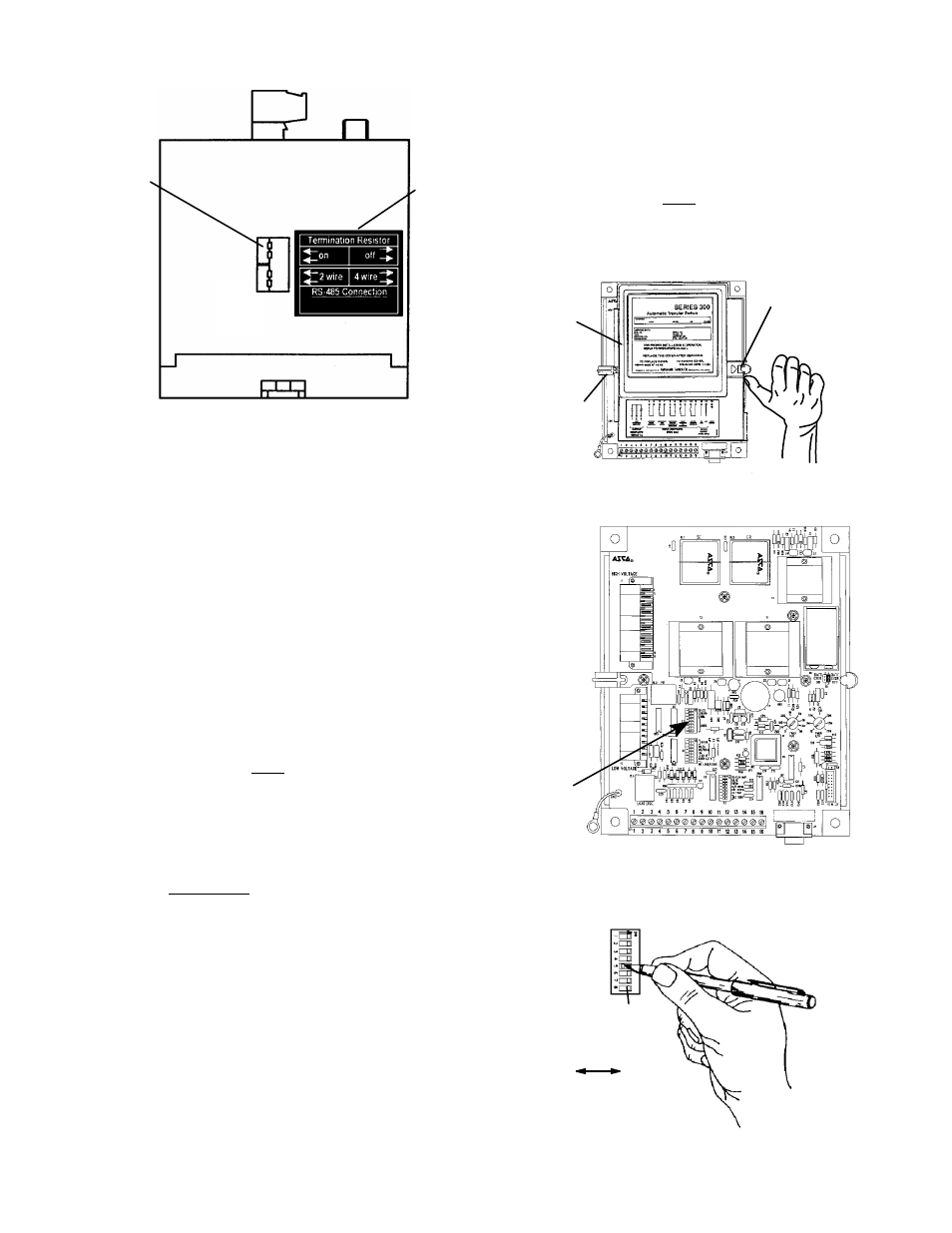
label
DIP
switches
Figure 4. Termination resistor DIP switches on
bottom of Serial Module. Must be ON for ATS
farthest away from the host device.
Setting the ATS Address
Set the communication address in the ATS controller.
Follow either the 4000 & 7000 Series procedure or the
Series 300 procedure below. Use Table D to record the
address and other ATS information.
4000 & 7000 Series ATSs
1. Refer to Group 5 Controller User’s Guide 381333–126
pages 2–8 and 2–9 for how to set a unique address for
this Automatic Transfer Switch.
2. If ASCObus II protocol is used (such as used with VPi
computer software) and a Power Manager is included
with the ATS, the Power Manager must be
programmed with the same address as that selected for
the ATS Group 5 Controller connected to the Serial
Module.
However, if Modbus protocol is used and a Power
Manager is included with the ATS, the Power Manager
must be programmed with a different and unique
address (not the same as the address of the Controller).
For setting the address in Power Manager Xp refer to
Operator’s Manual 381333–199.
Series 300 ATSs
1. Remove the cover from the controller by releasing the
latch on the right side with your thumb. See Figure 5.
2. Locate DIP switch S3 (left center) and set a unique
address for this ATS. Use a ball---point pen (or similar
pointed tool) to slide the switch actuators left or right
so that they match the illustration next to the setting
(left=off, right=on). Recheck the setting. See Figures
6 and 7, and refer to Table C on the next page.
3. Reinstall the cover on the controller by hooking it on
the left side and latching the right side.
4. The Series 300 ATS Group 1 Controller uses ASCO-
bus II protocol. Therefore, if a Power Manager is
included with the ATS, the Power Manager must be
programmed with the same address as that selected for
the ATS Group 1 Controller connected to the Serial
Module. Refer to Operator’s Manual 381333–199.
thumb
latch
cover
hook on
left side
Figure 5. Group 1 Controller cover latch.
S3 DIP
switch
Figure 6. Location of S3 DIP switch in
Group 1 Controller (Series 300 ATSs).
DIP
switch
SW3
actuator
on
off
(8 on each DIP switch)
Figure 7. Setting DIP switch actuators.